Power management circuit, method and system
A power management and power conversion circuit technology, which is applied in the direction of circuits or fluid pipelines, road transportation emission reduction, efficient vehicle charging, etc., can solve the problem of large static power consumption, achieve static power consumption control, low energy consumption, Effect of Reducing Static Power Consumption
- Summary
- Abstract
- Description
- Claims
- Application Information
AI Technical Summary
Problems solved by technology
Method used
Image
Examples
Embodiment 1
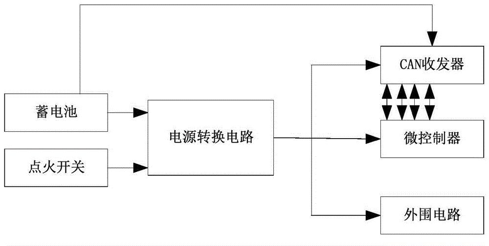
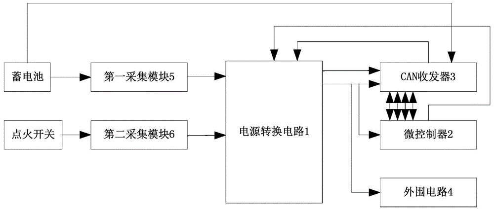
[0053] This embodiment provides a power management circuit, such as figure 2 As shown, it includes a power conversion circuit 1 , a microcontroller 2 and a CAN transceiver 3 .
[0054] The microcontroller 2 is used to control the CAN transceiver 3 to enter the dormant mode when the vehicle is parked or charged, so as to make itself and the power conversion circuit 1 both enter the dormant mode.
[0055] The CAN transceiver 3 is used to detect whether there is a wake-up signal, and enter the wake-up mode from the sleep mode when the wake-up signal is detected, so that the microcontroller 2 and the power conversion circuit 3 both enter the wake-up mode.
[0056] The power conversion circuit 1 includes a first output terminal and a second output terminal, and the first output terminal is used to supply power to the microcontroller 2, the CAN transceiver 3 and the peripheral circuit 4; the first output terminal The two output terminals output constant power, which are coupled wi...
Embodiment 2
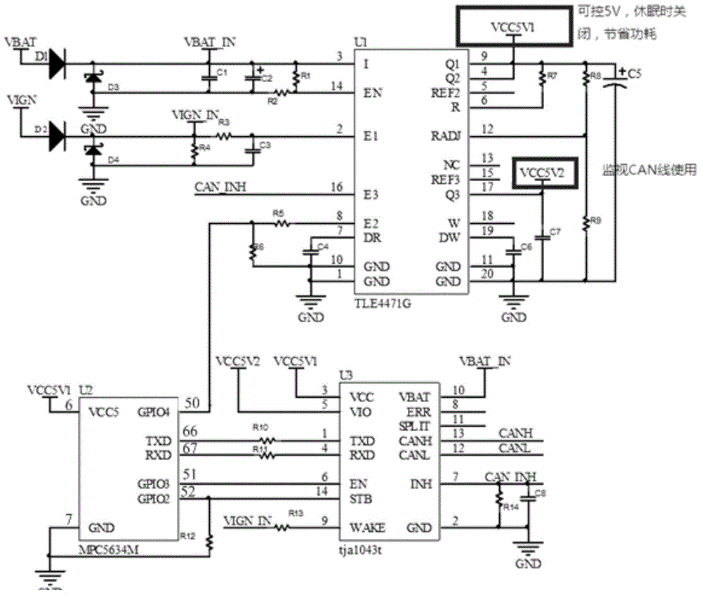
[0069] On the basis of Embodiment 1, the power management circuit described in this embodiment, such as image 3 As shown, the power conversion circuit 1 includes a power conversion chip U1, which includes 20 pins, resistors R5, R6, R7, R8, R9, capacitors C4, C6, C7, and a voltage stabilizing capacitor C5.
[0070] The pin 9 of the power conversion chip U1 is connected to the pin 4 as the first output end; the pin 17 of the power conversion chip U1 is the second output end; one end of the resistor R7 is connected to the The first output end is connected, the other end is connected to the pin 6 of the power conversion chip U1, one end of the resistor R8 is connected to the first output end, and the other end of the resistor R8 is connected to the power conversion chip U1 at the same time. The pin 12 of the chip U1 is connected to one end of the resistor R9, the other end of the R9 is grounded, one end of the capacitor C6 is connected to the pin 19 of the power conversion chip U...
Embodiment 3
[0091] This embodiment provides a power management method, including the following steps:
[0092] When the vehicle is in the parking or charging state, the CAN transceiver is controlled to enter the sleep mode, and then the power conversion circuit and the microcontroller are all entered into the sleep mode, and then the power supply voltage of the CAN transceiver, the power conversion circuit, the microcontroller and the peripheral circuit is Low, but the wake-up voltage of the CAN transceiver remains high.
[0093] Detect whether there is a wake-up signal, and when a wake-up signal is detected, the CAN transceiver enters the wake-up mode from the sleep mode, and then the microcontroller and the power conversion circuit enter the wake-up mode. At this time, the CAN transceiver, the power conversion circuit, the microcontroller The power supply voltage of the controller and peripheral circuits is high level.
[0094] In a specific application, judging whether the vehicle is ...
PUM
 Abstract
Description
Claims
Application Information
 - R&D
- Intellectual Property
- Life Sciences
- Materials
- Tech Scout
- Unparalleled Data Quality
- Higher Quality Content
- 60% Fewer Hallucinations
Browse by: Latest US Patents, China's latest patents, Technical Efficacy Thesaurus, Application Domain, Technology Topic, Popular Technical Reports.
© 2025 PatSnap. All rights reserved.Legal|Privacy policy|Modern Slavery Act Transparency Statement|Sitemap|About US| Contact US: help@patsnap.com


