Brake cooling method and brake cooling device

A technology of a cooling device and a cooling method, applied in the directions of brakes, cooling brakes, transportation and packaging, etc., can solve the problems of uneven thermal deformation, low cooling efficiency, affecting vehicle safety, etc., to avoid large temperature differences and improve cooling efficiency. , to avoid the effect of slippery road

Inactive Publication Date: 2015-08-26
WEICHAI POWER CO LTD
View PDF6 Cites 9 Cited by
  • Summary
  • Abstract
  • Description
  • Claims
  • Application Information

AI Technical Summary

Problems solved by technology

However, due to the inability to accurately control the amount of water and the large amount of water sprayed by the direct spray type, the cooling water sprayed on the brake drum cannot be completely evaporated, the cooling efficiency is low, and part of the cooling water flows to the road surface, causing the road surface to be slippery, affecting traffic safety, and , in the actual braking process, the inner side of the brake drum will generate a lot of heat to make its temperature very high, while the temperature of the cooling water is close to the air tem

Method used


Image

  • Brake cooling method and brake cooling device
  • Brake cooling method and brake cooling device
  • Brake cooling method and brake cooling device

Examples


Example Embodiment

[0042] Example one

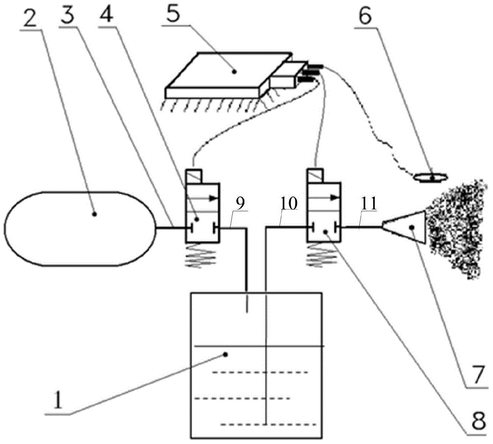
[0043] Please refer to figure 1 , figure 1 This is a schematic structural diagram of a brake cooling device provided in Embodiment 1 of the present invention, and the brake cooling device specifically includes:

[0044] Gas storage cylinder 2, used to store high-pressure gas;

[0045] It should be noted that the high-pressure gas stored in the air storage cylinder 2 refers to the air that can make the cooling water in the water tank 1 reach the spray nozzle 7 and spray it. This embodiment does not specify the pressure value of the air. Strictly limited, the same applies to other embodiments of the present invention;

[0046] A first solenoid valve 4 connected to the air tank 2 at one end and connected to the water tank 1 at the other end;

[0047] The water tank 1 with one end connected to the first solenoid valve 4 and the other end connected to the second solenoid valve 8;

[0048] It should be noted here that the brake cooling device provided in the first embodim...

Example Embodiment

[0074] Example two

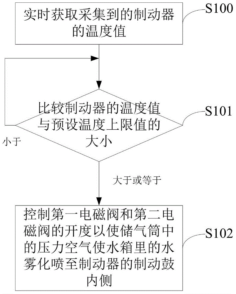
[0075] Based on the brake cooling device disclosed in the above embodiment and figure 1 As shown in the schematic structural diagram of the brake cooling device, the second embodiment of the present invention provides a brake cooling method, such as figure 2 Said, the method specifically includes the following steps:

[0076] Step S100: Acquire the collected temperature value of the brake in real time;

[0077] Specifically, the controller obtains the temperature value of the brake drum of the brake collected by the temperature collector 6 in real time;

[0078] It should be noted that the execution subject of the execution steps in each embodiment of the present invention is a controller, that is, unless otherwise specified, the execution steps in each embodiment are all completed by the controller;

[0079] Step S101, comparing the temperature value of the brake with a preset temperature upper limit value, and when the comparison result is that the temperature va...

Example Embodiment

[0093] Example three

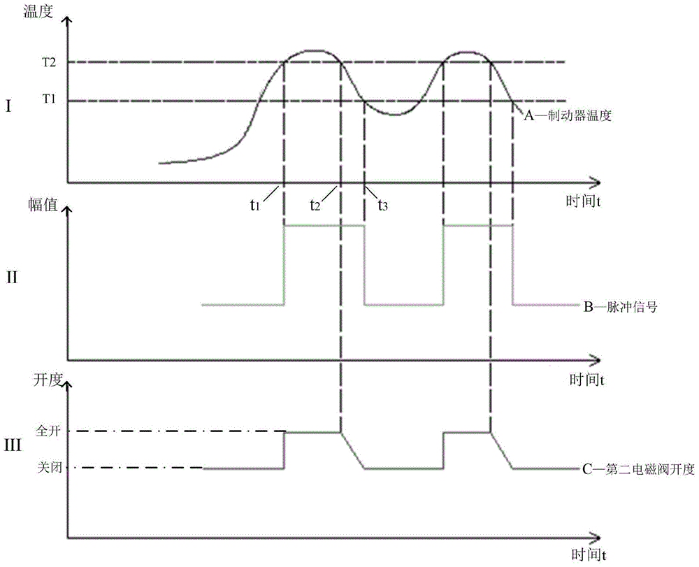
[0094] Based on the brake cooling method disclosed in the second embodiment above, step S102 is executed to control the opening of the first solenoid valve 4 and the second solenoid valve 8 so that the compressed air in the air reservoir 2 makes the water in the water tank 1 The water is atomized and sprayed to the inside of the brake drum of the brake through the spray nozzle 7, including:

[0095] Step S200, controlling the opening degree of the first solenoid valve 4 to be fully open, so that the pressurized gas in the air tank 2 enters the water tank 1;

[0096] Step S201, controlling the opening degree of the second solenoid valve 8 to be fully open, and performing a logical subtraction operation on the current temperature value of the brake and a preset temperature lower limit, and according to the operation result obtained by the logical subtraction operation The opening degree of the second solenoid valve 8 is controlled to adjust the amount of water a...


PUM


Abstract

The invention discloses a brake cooling method and a brake cooling device. Collected temperature values of a brake are obtained in real time through a controller (5); when the temperature value of the brake is greater than a preset temperature value, the opening degree of a first electromagnetic valve (4) and the opening degree of a second electromagnetic valve (8) are controlled, so that water in a water tank (1) is atomized and sprayed to the inner side of a brake drum of the brake by an atomizing spray head (7) through pressured air in an air storage tube (2); the goals of regulating and controlling the quantity of cooling water according to the temperature condition of the brake, reasonably and effectively using cooling water, further improving the cooling efficiency, avoiding wet and slippery conditions of the pavement caused by the cooling water and saving water resources are achieved; the goals of atomizing the cooling water and uniformly spraying the cooling water to the inner side of the brake drum are achieved by using the atomizing spray head; the problem of local cracking due to greater temperature differences at the inner and outer sides of the brake drum caused by direct showering type cooling is effectively avoided; and the running safety of vehicles is further improved.

Description

technical field [0001] The invention relates to the technical field of automobile brakes, in particular to a brake cooling method and device. Background technique [0002] Today, the brake cooling device occupies a major position among the factors that ensure that the automobile braking system has better braking performance during the braking process. [0003] At present, for the cooling problem of the traditional drum brake during the braking process, the way of cooling water directly pouring the brake drum is usually used, that is, the cooling water in the water tank is directly poured to the brake drum of the drum brake through the water pipe. on the outside of the drum. However, due to the inability to accurately control the amount of water and the large amount of water sprayed by the direct spray type, the cooling water sprayed on the brake drum cannot be completely evaporated, the cooling efficiency is low, and part of the cooling water flows to the road surface, caus...

Claims


Application Information

Patent Timeline
IPC IPC(8): B60T5/00
CPCB60T5/00
Inventor 崔红雨祝彦寿国举强高秀波毛洪海
Owner WEICHAI POWER CO LTD
Why Eureka
Try Eureka