Dual-sliding-body synchronous movement device

A synchronous motion and double-sliding technology, applied in engine control, combustion engine, machine/engine, etc., can solve problems such as inability to realize intake tumble flow self-regulation, and achieve the effect of simple structure and reasonable design

Inactive Publication Date: 2015-08-26
王振华
View PDF0 Cites 0 Cited by
  • Summary
  • Abstract
  • Description
  • Claims
  • Application Information

AI Technical Summary

Problems solved by technology

[0003] After searching the existing literature, it is found that the patent application number is 20121041673.5, and the name is a patented technology of a variable intake tumble a...

Method used


Image

  • Dual-sliding-body synchronous movement device
  • Dual-sliding-body synchronous movement device
  • Dual-sliding-body synchronous movement device

Examples


Embodiment

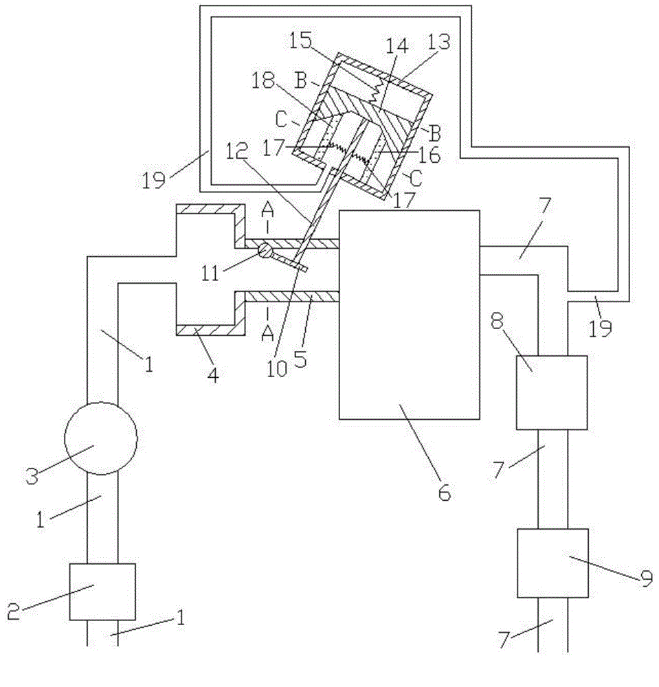
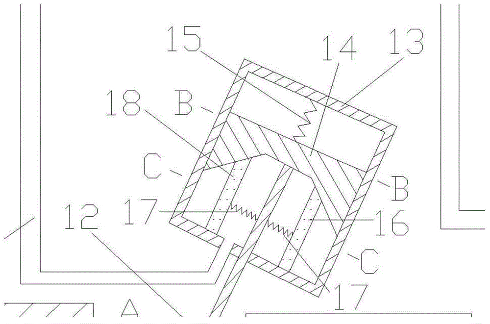
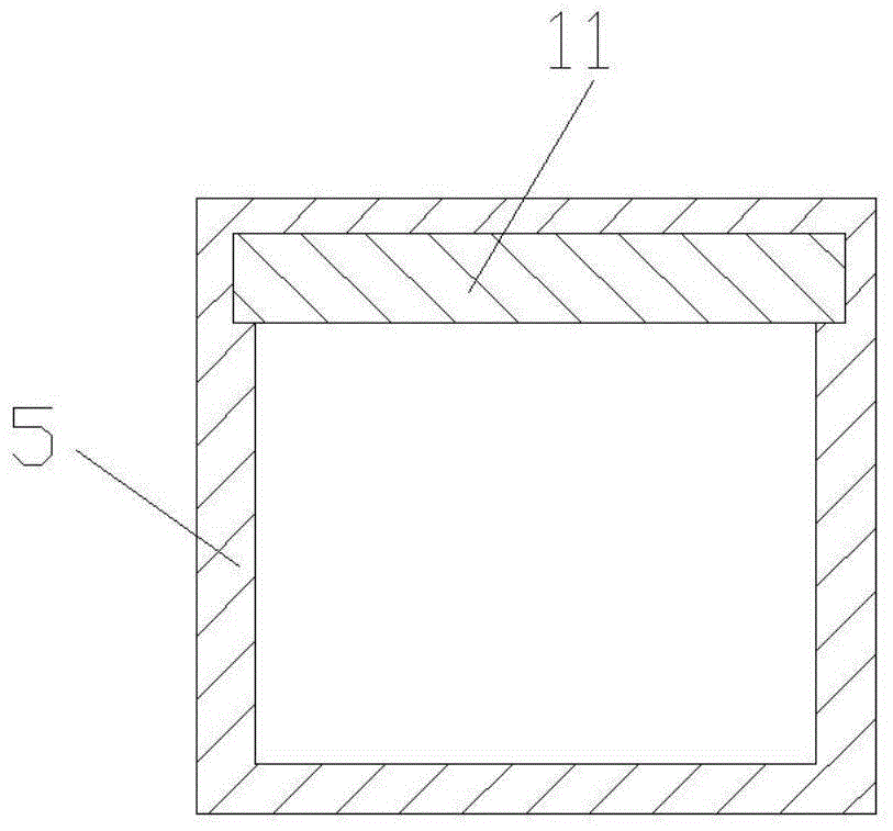
[0015] Examples of the present invention are Figure 1 to Figure 5 As shown, the present invention includes engine intake pipe 1, air filter 2, throttle valve 3, intake main pipe 4, intake branch pipe 5, engine 6, engine exhaust pipe 7, catalytic package 8, muffler 9, guide vane plate 10 , rotating shaft 11, push-pull rod 12, control body 13, moving body 14, first spring 15, first sliding body 16, second spring 17, second sliding body 18, connecting pipe 19, the air outlet of engine intake pipe 1 It is connected with the air inlet of the air intake main pipe 4, the air outlet of the air intake main pipe 4 is connected with the air inlet of the air intake branch pipe 5, the air outlet of the air intake branch pipe 5 is connected with the air intake of the engine 6, and the air filter 2. The throttle valve 3 is sequentially connected to the engine intake pipe 1, the air outlet of the engine exhaust pipe 7 is connected to the exhaust passage of the engine 6, and the catalytic pac...


PUM


Abstract

A dual-sliding-body synchronous movement system belongs to the technical field of internal combustion engines and comprises an engine intake pipe, an engine, an engine exhaust pipe, a guide-leaf plate, a rotating shaft, a push-pull rod, a control body, springs, a moving body, sliding bodies and a connecting pipe, wherein the guide-leaf plate is arranged in an air inlet branch and fixedly connected with the rotating shaft; one end of the push-pull rod is hinged to the guide-leaf plate, and the other end of the push-pull rod is hinged to the moving body after penetrating the lower wall surface of the control body; the sliding bodies are connected through the springs; one end of the connecting pipe is communicated with the lower cavity of the control body, and the other end of the connecting pipe is communicated with the engine exhaust pipe, between a catalyst pack and a noise damper. When the engine works under the low-speed working condition, intake flow tumbling is relatively strong; when the engine works under the high-speed working condition, the pumping loss is low. The dual-sliding-body synchronous movement system is reasonable in design, simple in structure and suitable for optimal design of the air intake system of a naturally aspirated engine.

Description

technical field [0001] The invention belongs to the technical field of internal combustion engines, and in particular relates to a double sliding body synchronous movement device capable of realizing self-regulation of an air intake system of a naturally aspirated engine. Background technique [0002] At the beginning of the 20th century, British B. Hopkinson found in the internal combustion engine test that when the air in the cylinder is disturbed, the combustion process can be accelerated Effect, the use of tumble flow to increase the turbulence intensity in the combustion chamber and the use of lean mixture combustion mode, etc., have become the focus of research on spark ignition engines. The air movement in the engine cylinder is transient and complex. From the point of view of the overall movement of the gas macroscopically, it generally appears as an oblique axis vortex. At this time, the vortex and tumble can be regarded as two independent components of the oblique...

Claims


Application Information

Patent Timeline
IPC IPC(8): F02D9/10F02B31/04
CPCY02T10/12
Inventor 王振华
Owner 王振华
Why Eureka
Try Eureka