Self-cleaning method for EGR valve

An EGR valve, self-cleaning technology, used in electrical control, machine/engine, fuel injection control, etc., can solve problems such as inability to effectively remove carbon deposits, dirt, EGR valve deposits, and inability to achieve self-cleaning purposes.

Active Publication Date: 2015-08-26
WEICHAI POWER CO LTD
View PDF9 Cites 24 Cited by
  • Summary
  • Abstract
  • Description
  • Claims
  • Application Information

AI Technical Summary

Problems solved by technology

However, this method cannot effectively remove the deposits on the valve plate and valve body of the EGR valve. Especially during the self-learning process of the EGR valve, in order to effectively protect the EGR valve and avoid damage, a soft Seated to reduce vibration, friction, etc.
Therefore, the existing EGR valve cannot effectively remove the carbon deposits and dirt accumulated on the EGR valve, and cannot achieve the real self-cleaning purpose at all.

Method used


Image

  • Self-cleaning method for EGR valve
  • Self-cleaning method for EGR valve
  • Self-cleaning method for EGR valve

Examples


Embodiment Construction

[0028] The core of the present invention is to provide a self-cleaning method for an EGR valve, through which deposits accumulated in the EGR valve can be effectively eliminated, a stable and reliable working state of the EGR valve can be ensured, and its service life can be improved.

[0029] In order to enable those skilled in the art to better understand the technical solutions of the present invention, the present invention will be further described in detail below in conjunction with the accompanying drawings and specific embodiments.

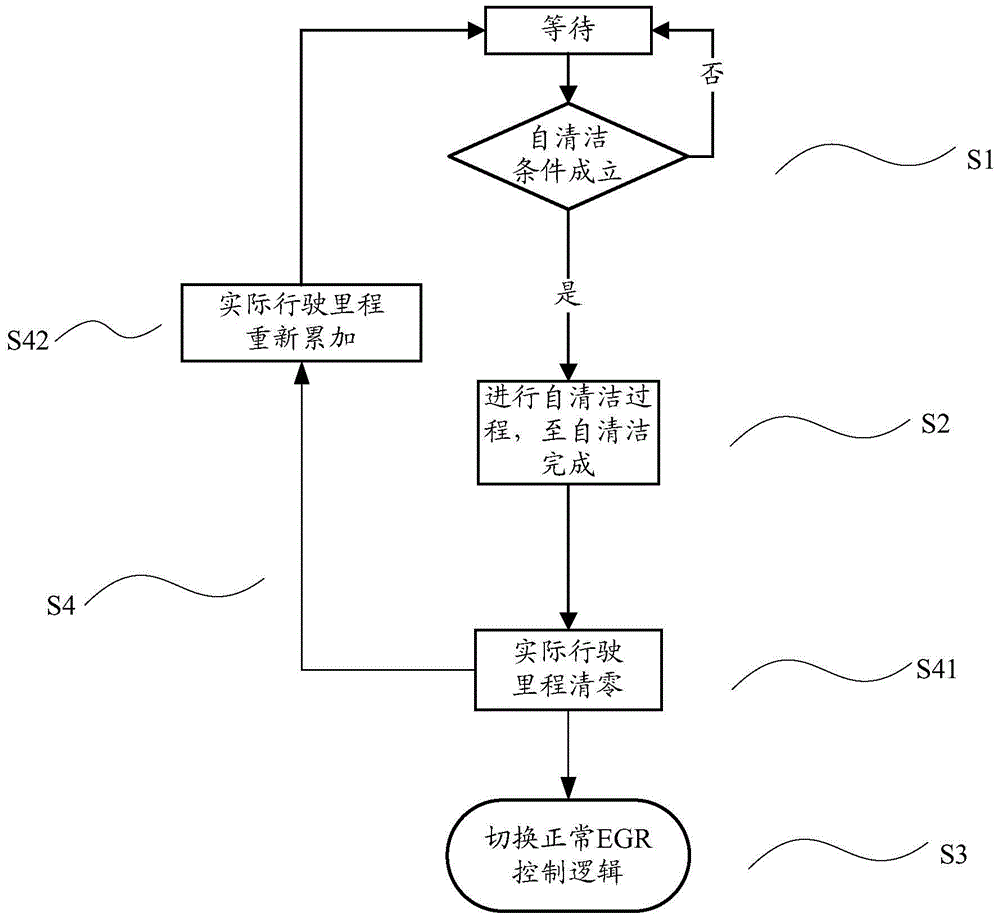
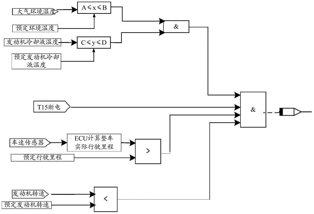
[0030] Please refer to figure 1 , figure 2 ,in, figure 1 It is the control logic diagram of the EGR valve self-cleaning in the specific embodiment; figure 2 It is a logical diagram of activation conditions of EGR valve self-cleaning in a specific embodiment.

[0031] The invention provides a self-cleaning method of an EGR valve, and the ECU of the engine controls the action of the EGR valve. In a specific embodiment, such as figure ...


PUM


Abstract

The invention discloses a self-cleaning method for an EGR valve. An ECU of an engine controls action of the EGR valve, the self-cleaning method comprises the steps that the ECU sends a preset command signal to control the self-cleaning action of the EGR valve, and the EGR valve conducts fully closing action and fully opening action to produce vibration till the self-cleaning process is over. By means of the self-cleaning method, sediments gathered on the EGR valve are effectively removed, the stable and reliable working state of the EGR valve is guaranteed, and the service life of the EGR valve is prolonged.

Description

technical field [0001] The invention relates to the technical field of EGR valves, in particular to a self-cleaning method for an EGR valve. Background technique [0002] EGR (Exhaust Gas Recirculation) is exhaust gas recirculation, that is, the exhaust gas from the engine is reintroduced into the intake pipe and mixed with fresh gas to enter the combustion chamber for combustion. [0003] The EGR valve is installed on the engine to control the amount of recirculated exhaust gas entering the intake system. The on-board ECU (Electronic Control Unit) adjusts the opening of the EGR valve to precisely control the amount of exhaust gas entering the engine. It can be seen that the EGR valve is exposed to the exhaust gas environment for a long time, causing it to easily generate carbon deposits and dirt; especially the EGR valve installed behind the EGR exhaust gas cooler, that is, the cold end EGR valve, because the exhaust gas temperature here is very low, each This exhaust gas...

Claims


Application Information

Patent Timeline
Patent Type & Authority Applications(China)
IPC IPC(8): F02D41/00
Inventor 栾军山李峰
Owner WEICHAI POWER CO LTD
Why Eureka
Try Eureka