A Time Grating Angular Displacement Sensor

A technology of angular displacement sensor and time grating, which is applied in the direction of instruments, measuring devices, and electric devices, etc., can solve the problems of high cost and insufficient resolution, and achieve the effects of low cost, high measurement accuracy and improved measurement resolution

Active Publication Date: 2017-05-24
CHONGQING UNIV OF TECH
View PDF9 Cites 2 Cited by
  • Summary
  • Abstract
  • Description
  • Claims
  • Application Information

AI Technical Summary

Problems solved by technology

However, if it is necessary to further improve its resolution, it can only be realized by reducing the spatial pole distance or increasing the number of pole pairs of the sensor. For example, a multi-pole planar winding time grid angular displacement sensor disclosed by CN2909178Y adopts an ironless multi-pole Pole plane windings improve the linearity of the rotating magnetic field by increasing the number of pole pairs of the sensor, which can reduce interference and high-frequency distortion, and improve the accuracy and resolution of the time grid angular displacement sensor, but its cost is relatively high
[0003] CN102425987A discloses a time grating angular displacement sensor based on an alternating electric field, which adopts a differential plate capacitive structure, uses the electric field coupling principle to acquire signals to measure angular displacement, has low power consumption, light weight, and low cost, but its resolution still not high enough

Method used


Image

  • A Time Grating Angular Displacement Sensor
  • A Time Grating Angular Displacement Sensor
  • A Time Grating Angular Displacement Sensor

Examples


Embodiment 1

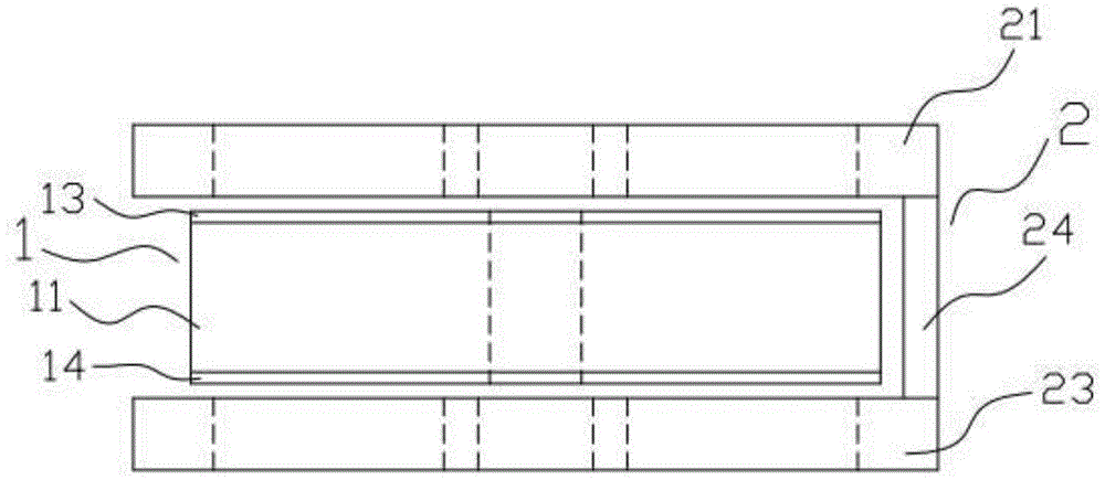
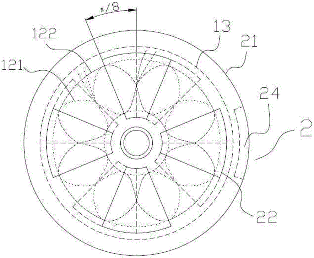
[0029] Example 1: as Figure 1 to Figure 7The shown time grid angular displacement sensor includes stator 1 and rotor 2.

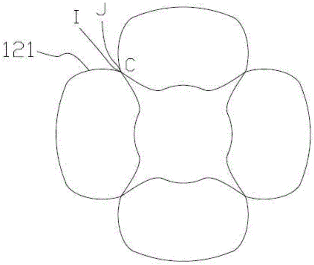
[0030] The stator 1 is composed of a stator base 11 and two identical sensing units 12. The stator base 11 is a magnetically conductive cylinder with an axial hole in the center. The magnetically conductive cylinder is made of magnetically conductive material iron, and its height is 10mm. The induction unit 12 includes an excitation coil 121 and an induction coil 122. The excitation coil 121 and the induction coil 122 adopt a printed circuit wiring method. The upper end face of the stator base 11 is fixed with an upper printed circuit board 13 that matches the shape of the stator base. The excitation coil 121 and the induction coil 122 of the sensing unit 12 are independently arranged on different wiring layers of the upper printed circuit board 13. The lower end surface of the stator base 11 is fixed with a lower printed circuit board 14 that matches the ...

Embodiment 2

[0047] Example 2: as Figure 8 , Figure 9 As shown in the figure, the structure of the time grid angle displacement sensor is mostly the same as that of the first embodiment, the difference is: the starting position of the excitation coil 121 of the sensing unit arranged on the upper printed circuit board 13 (corresponding to Figure 8 G point in ) and the starting position of the excitation coil 121 of the sensing unit arranged on the lower printed circuit board 14 (corresponding to Figure 8 The central angle contained by the H point in the upper printed circuit board) is α, and the value of α is not 0; the initial position of the induction coil 122 of the sensing unit arranged on the upper printed circuit board Figure 8 R point in the ) and the starting position of the induction coil 122 of the sensing unit arranged on the lower printed circuit board 14 (corresponding to Figure 8 The central angle contained by the T point in the middle is α; the initial position of the...

Embodiment 3

[0055] Embodiment 3: The structure of the time grating angular displacement sensor is mostly the same as that of Embodiment 1, the difference is that the magnetic conduction unit is composed of a magnetic conduction body 22; The excitation coil 121 and the induction coil 122 of the sensing unit are insulated from each other and embedded in the upper embedding groove according to their respective winding methods; The induction coils 122 are insulated from each other and embedded in the lower wire groove according to their respective winding methods.


PUM


Abstract

The invention discloses a time grating angular displacement sensor, comprising a stator and a rotor. The stator is formed by a stator substrate and two same sensing units. The two sensing units are parallel and are arranged on the upper end face and the lower end face of the stator substrate in a non-interfering manner. The sensing unit comprises an exciting coil and an induction coil. Wires are winded on the exciting coil and the induction coil in a lying 8 shaped winding method. The induction coils of the two sensing units are connected in series. The rotor is formed by an upper rotor substrate, a lower rotor substrate, a support column, and two same magnetic conductive units. The two magnetic conductive units are respectively embedded on the upper rotor substrate and the lower rotor substrate and are parallel to each other. The magnetic conductive unit is formed by winding a magnetizer or m same magnetizers on the shaft axis of the upper rotor substrate or the lower rotor substrate in equal interval arrangement. The initial positions of the magnetizers in the two magnetic conductive units satisfy specific conditions. The time grating angular displacement sensor can improve measurement resolution by double under the condition of not increasing reticle precision or number of pole-pairs of a sensor.

Description

technical field [0001] The invention belongs to the technical field of precision measurement sensors, in particular to a time grid angular displacement sensor. Background technique [0002] Precision angular displacement measurement usually uses various angular displacement sensors, such as grating, tooth grid, capacitive grid and so on. They mainly improve the measurement resolution through two ways: one is to increase the spatial scribe density and reduce the spatial grating pitch; the other is to increase the electronic subdivision multiple. In recent years, a time grating angular displacement sensor based on the principle of electromagnetic induction has appeared. Different from the above angular displacement sensor, the time grating angular displacement sensor uses the clock pulse as the measurement reference, so its resolution depends on the spatial pole distance of the sensor on the one hand. On the other hand, it also depends on the space equivalent of the interpola...

Claims


Application Information

Patent Timeline
Patent Type & Authority Patents(China)
IPC IPC(8): G01B7/30
Inventor 鲁进陈锡侯武亮汤其富
Owner CHONGQING UNIV OF TECH
Why Eureka
Try Eureka