Continuous loading rock mechanical device matched with X-optical mechanical scanning

A rock mechanics, optomechanical technology, applied in the application of stable tension/pressure testing material strength, using radiation for material analysis, etc., can solve the problems of inconvenient movement, small loading capacity, large volume, etc. Analysis, reasonable structure, flexible and easy operation

Inactive Publication Date: 2015-08-26
XIAN UNIV OF SCI & TECH
View PDF9 Cites 2 Cited by
  • Summary
  • Abstract
  • Description
  • Claims
  • Application Information

AI Technical Summary

Problems solved by technology

[0003] The existing continuous loading rock mechanics test device is a complete set of independent mechanical test system, which adopts servo motor and oil pump to control the loading mode, which is bulky and inconvenient to move
In addition, the rock loading test devices under X-ray scanning conditions are all developed based on the CT tomography equipment platform, and their loading capacity is small (the maximum axial loading force is 400KN); methods and test conditions, the vast majority of device development is purely mechanical tests or CT scanning of rock samples under laboratory conditions, and the realization of hydraulically controlled continuous high-pressure loading and supporting X-ray machines to scan rock samples has become a technology problem

Method used


Image

  • Continuous loading rock mechanical device matched with X-optical mechanical scanning
  • Continuous loading rock mechanical device matched with X-optical mechanical scanning
  • Continuous loading rock mechanical device matched with X-optical mechanical scanning

Examples


Embodiment Construction

[0022] In order to make the object, technical solution and advantages of the present invention clearer, the present invention will be further described in detail below in conjunction with the accompanying drawings and embodiments. It should be understood that the specific embodiments described here are only used to explain the present invention, not to limit the present invention.

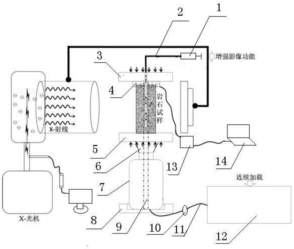
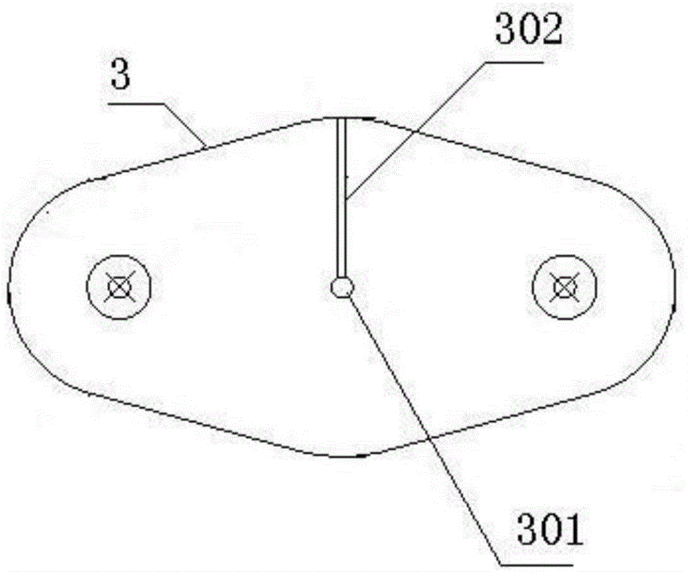
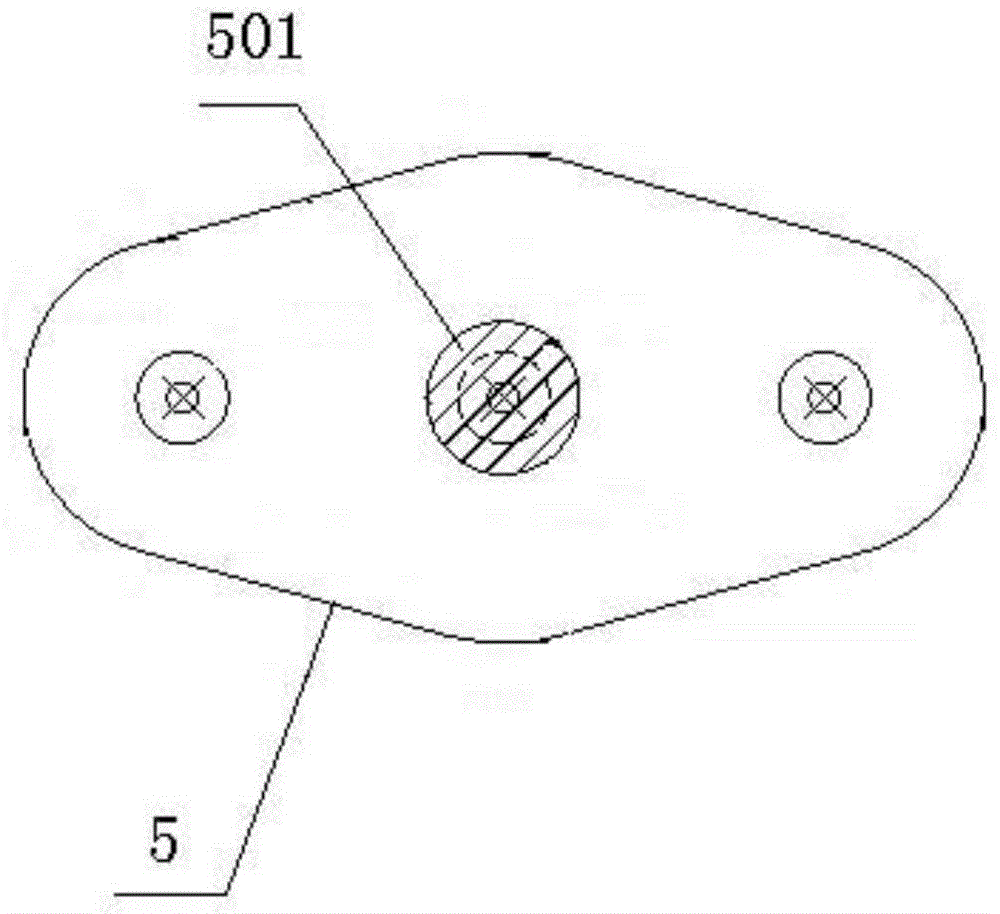
[0023] refer to Figure 1-Figure 5 It can be seen that the continuous loading rock mechanics device for X-ray machine scanning includes an enhanced image system and a continuous control loading system. The enhanced image system includes a constant pressure injector 1, a capillary 2 and a contrast agent (not shown in the figure), The continuous control loading system includes an experimental loading platform, a separate hydraulic jack 7, a hydraulically controlled loading oil pump 12, a spoke pressure sensor 4, a digital display meter 13 and a computer 14. The experimental loading platform consists ...


PUM

PropertyMeasurementUnit
widthaaaaaaaaaa
diameteraaaaaaaaaa
diameteraaaaaaaaaa

Abstract

The invention relates to a continuous loading rock mechanical device matched with X-optical mechanical scanning. An enhanced image system comprises a constant-pressure injector, a capillary tube and a contrast agent; a continuous control loading system comprises an experiment loading platform, a separation type hydraulic jack, a hydraulic control loading oil pump, a spoke pressure sensor, a digital display gauge and a computer; the experiment loading platform is formed by connecting a top seat, a bottom seat, a loading disc and a stress uniform distribution weight through a column rod; the separation type hydraulic jack is connected with the hydraulic control loading oil pump through an oil pipe; the oil pipe is provided with a flow meter; the capillary tube is connected with the constant-pressure injector and the experiment loading platform respectively; the contrast agent is injected into a test piece sample in the experiment loading platform through the constant-pressure injector and the capillary tube; the spoke pressure sensor is connected with the digital display gauge through an electric lead wire; and the digital display gauge is electrically connected with the computer. By virtue of the continuous loading rock mechanical device, data can be conveniently induced and analyzed; and the continuous loading rock mechanical device has a small volume and is convenient to move; and high-definition DR/CR image scanning pictures can be obtained, and quantitative analysis is convenient to realize.

Description

technical field [0001] The invention relates to the technical field of mining engineering, in particular to a continuous loading rock mechanics device matched with X-ray machine scanning. Background technique [0002] The study of damage characteristics of mine rock mass is one of the frontier topics in the field of rock mechanics. The research on the mesoscopic damage mechanics of coal (rock) in mines is to study the shape, distribution and evolution characteristics of various types of damage from the micro-cracks and cavities in the collected coal (rock) samples. In recent years, with the development of X-ray machine equipment research and development technology, this equipment has been continuously used in damage testing in various engineering fields. Especially the application of CT scanning imaging technology, relevant researchers at home and abroad have applied this technical means to engineering fields such as rock, concrete and frozen soil. [0003] The existing co...

Claims


Application Information

Patent Timeline
Patent Type & Authority Applications(China)
IPC IPC(8): G01N3/12G01N23/04
Inventor 孙欢来兴平单鹏飞毋凡
Owner XIAN UNIV OF SCI & TECH
Why Eureka
Try Eureka