Eureka AIR delivers breakthrough ideas for toughest innovation challenges, trusted by R&D personnel around the world.

Software configuration item test method and system

A software configuration and testing system technology, applied in the direction of software testing/debugging, etc., can solve the problems that cannot truly reflect the actual characteristics of the device, cannot guarantee the ability and time accuracy, and spend a lot of testing time, so as to save testing resources, low cost, The effect of addressing limitations

Active Publication Date: 2015-08-26
TECH & ENG CENT FOR SPACE UTILIZATION CHINESE ACAD OF SCI
View PDF7 Cites 10 Cited by
  • Summary
  • Abstract
  • Description
  • Claims
  • Application Information

AI Technical Summary

Problems solved by technology

[0002] There are two main types of simulation test systems currently used for testing software configuration items. One is based on virtualization platform simulation with script testing. This kind of test system often cannot truly reflect the actual characteristics of the device itself, and the input stimulus is too ideal. The test object has ignored the electrical characteristics, and the output signal may not reflect the real state of the test object. In addition, the simulation and script test method need to spend a lot of test time, and the test efficiency is low;
[0003] The second main test system is the hardware-in-the-loop simulation test system based on the interface. This system basically uses a general-purpose independent interface board. Although this test system can reflect the actual characteristics of the real physical device, the task-driven configuration item High-level embedded system testing requires precise cooperation between interfaces, and the ability and time accuracy of interface-based test systems to work together cannot be guaranteed.

Method used


Image

  • Software configuration item test method and system
  • Software configuration item test method and system
  • Software configuration item test method and system

Examples


Embodiment Construction

[0051] The principles and features of the present invention are described below in conjunction with the accompanying drawings, and the examples given are only used to explain the present invention, and are not intended to limit the scope of the present invention.

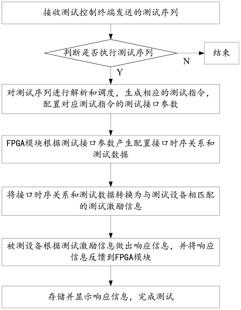
[0052] Such as figure 1 Shown, be the testing method of a kind of software configuration item described in the present invention, specifically comprise the following steps:

[0053] Step 1: Receive the test sequence sent by the test control terminal;

[0054] Step 2: Determine whether to execute the test sequence, if yes, execute step 3; otherwise, end;

[0055] Step 3: Analyze and schedule the test sequence, generate corresponding test instructions, and configure test interface parameters corresponding to the test instructions;

[0056] Step 4: The FPGA module generates configuration interface timing relationship and test data according to the test interface parameters;

[0057] Step 5: Convert the interface tim...


PUM


Abstract

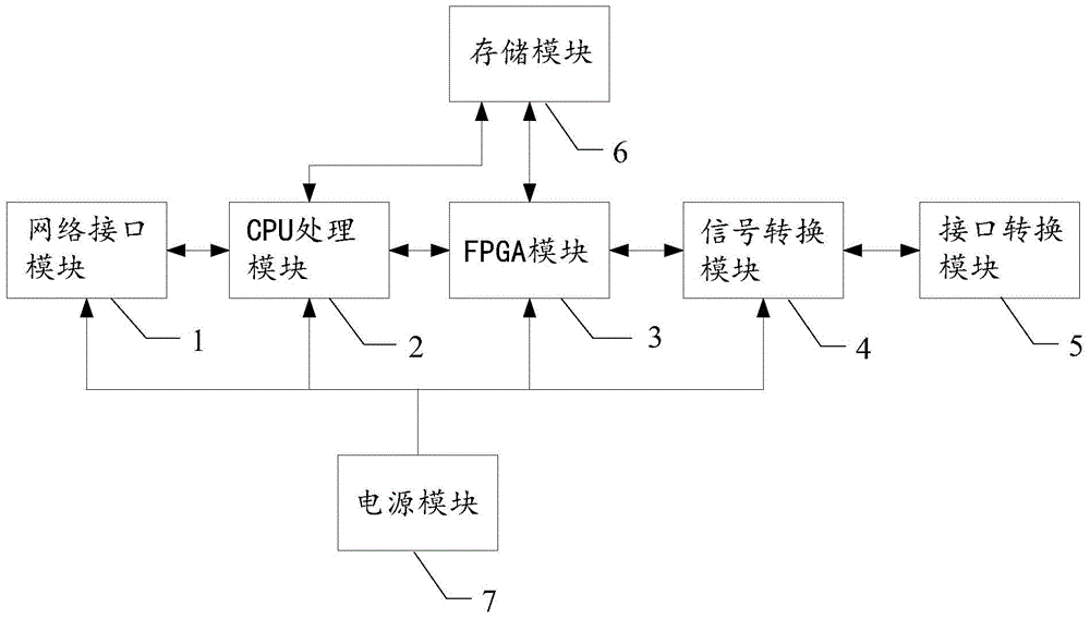
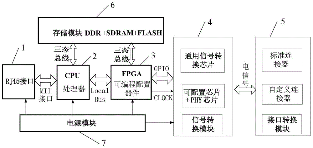
The present invention relates to a software configuration item test method and system. The system comprises: a network interface module, a CPU processing module, an FPGA module, a signal conversion module, an interface conversion module, and a storage module. The network interface module is configured to receive a test serial number sent by a test control terminal. The CPU processing module is configured to receive the test serial number, and parse and schedule the test serial number to generate a corresponding test instruction and thus to configure test interface parameters corresponding to the test instruction. The FPGA module is configured to generate configuration interface time sequence relationship and test data according to the test interface parameters. The signal conversion module is configured to convert the interface time sequence relationship and the test data into test excitation information matching with a test device. The interface conversion module is configured to feed back response information made by a tested device according to the test excitation information to the FPGA module. The storage module is configured to store the response information. The system and method according to the present invention have the advantages of portability, remote control and the like.

Description

technical field [0001] The invention relates to a testing method and system for software configuration items. Background technique [0002] There are two main types of simulation test systems currently used for testing software configuration items. One is based on virtualization platform simulation with script testing. This kind of test system often cannot truly reflect the actual characteristics of the device itself, and the input stimulus is too ideal. The test object has ignored the electrical characteristics, and the output signal may not reflect the real state of the test object. In addition, the simulation and script test method need to spend a lot of test time, and the test efficiency is low; [0003] The second main test system is the hardware-in-the-loop simulation test system based on the interface. This system basically uses a general-purpose independent interface board. Although this test system can reflect the actual characteristics of the real physical device, ...

Claims


Application Information

Patent Timeline
Patent Type & Authority Applications(China)
IPC IPC(8): G06F11/36
Inventor 周珊王彬王金波
Owner TECH & ENG CENT FOR SPACE UTILIZATION CHINESE ACAD OF SCI
Why Eureka
Eureka Blog
Learn More