30 degree parallel lens used for ion implanter

An ion implanter and parallel lens technology, applied in the direction of discharge tubes, electrical components, circuits, etc., can solve the problem of inability to meet the requirements of higher parallelism of the process beam, the design of the yoke and coil is not optimized, and the shape of the magnetic pole face is unreasonable. and other problems, to achieve the effect of light weight, uniformity and repeatability, and low cost

Active Publication Date: 2015-08-26
BEIJING SHUOKE ZHONGKEXIN ELECTRONICS EQUIP CO LTD
View PDF5 Cites 2 Cited by
  • Summary
  • Abstract
  • Description
  • Claims
  • Application Information

AI Technical Summary

Problems solved by technology

[0005] Commonly used parallel lenses, the shape design of the magnetic pole surface is not reasonable enough to meet the beam parallelism requirements of higher technology. At the same time, the design of the yoke and coil is not optimized, and there are problems such as complex processing, heavy weight, high cost, and difficult assembly.

Method used


Image

  • 30 degree parallel lens used for ion implanter
  • 30 degree parallel lens used for ion implanter
  • 30 degree parallel lens used for ion implanter

Examples


Embodiment Construction

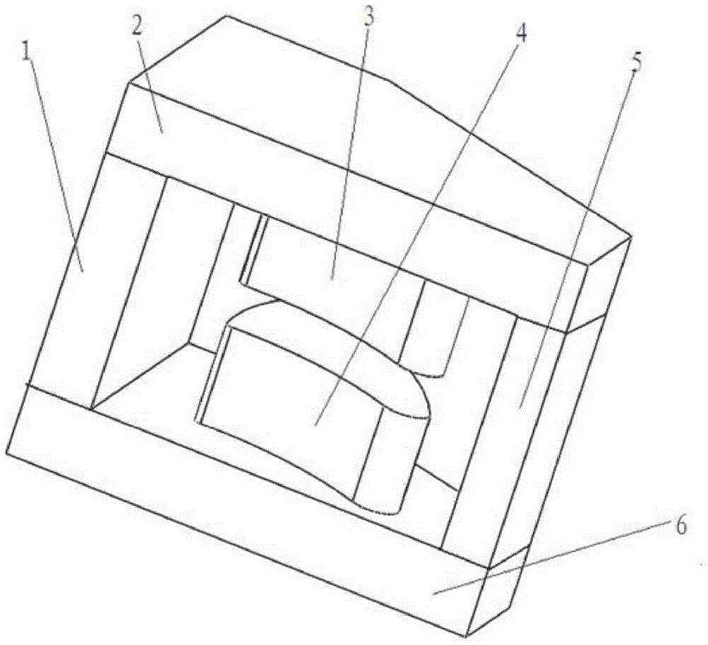
[0026] Such as figure 1 As shown, a 30° parallel lens for an ion implanter includes an upper magnetic pole 3 and a lower magnetic pole 4 with the same structure and size and installed symmetrically up and down. An upper magnetic yoke 2 and a lower magnetic pole 4 are arranged above the upper magnetic pole 3 A lower yoke 6 is provided below, the top surface of the upper magnetic pole 3 is connected to the bottom surface of the upper magnetic yoke 2, and the bottom surface of the lower magnetic pole 4 is connected to the top surface of the lower magnetic yoke 6; the parallel lens is also provided with two intermediate Yokes 1, 5, the tops of the two middle yokes 1, 5 are connected to the bottom surface of the upper yoke 2, and the bottom ends of the two middle yokes 1, 5 are connected to the top surface of the lower yoke 6, and The upper magnetic pole 3 and the lower magnetic pole 6 are placed between the two middle yokes 1, 5; the lower magnetic pole surface of the upper ...


PUM


Abstract

The invention relates to a 30 degree parallel lens used for an ion implanter. The parallel lens comprises an upper magnetic pole and a lower magnetic pole whose structures and sizes are consistent and which are arranged in a longitudinally symmetrical state. An upper magnet yoke is arranged above the upper magnetic pole. A lower magnet yoke is arranged below the lower magnetic pole. A top surface of the upper magnetic pole is connected to a bottom surface of the upper magnet yoke. A bottom surface of the lower magnetic pole is connected to a top surface of the lower magnet yoke. The parallel lens is provided with two intermediate magnet yokes. Top ends of the two intermediate magnet yokes are connected to the bottom surface of the upper magnet yoke. Bottom ends of the two intermediate magnet yokes are connected to the top surface of the lower magnet yoke. The upper magnetic pole and the lower magnetic pole are arranged between the two intermediate magnet yokes. A lower magnetic pole surface of the upper magnetic pole and an upper magnetic pole surface edge of the lower magnetic pole are formed by a plurality of trajectories. In the invention, shapes of the magnetic pole surfaces are reasonable; an ion beam injection angle can keep the same, and uniformity and repeatability are guaranteed; incident ions are prevented from generating a channel effect on a lattice structure of a semiconductor chip; and uniform and needed channels can be generated.

Description

technical field [0001] The invention relates to an ion implanter used in the semiconductor material ion implantation process in the field of semiconductor device manufacturing, in particular to a 30° parallel lens for the ion implanter. Background technique [0002] With the development of semiconductor integrated circuit manufacturing technology, the integration level is getting higher and higher, the circuit scale is getting bigger and bigger, and the size of individual components in the circuit is getting smaller and smaller, which puts forward higher requirements for semiconductor process equipment. As one of the key equipment in the semiconductor ion doping process line, the ion implanter also puts forward high requirements. Especially the requirements for energy pollution and ion pollution, the requirements for uniformity and repeatability, and the requirements for directional beam implantation are getting higher and higher. On the other hand, in order to improve prod...

Claims


Application Information

Patent Timeline
Patent Type & Authority Applications(China)
IPC IPC(8): H01J37/317H01J37/141
Inventor 张赛胡振东彭立波易文杰袁卫华孙雪平
Owner BEIJING SHUOKE ZHONGKEXIN ELECTRONICS EQUIP CO LTD
Why Eureka
Try Eureka