Automatic power-on intelligent-type electric leakage protector

A leakage protector and automatic power-on technology, applied in the direction of automatic disconnection emergency protection device, emergency protection circuit device, electrical components, etc., can solve the problems of leakage protector electric shock, affecting personal safety and other problems, and improve energy saving effect. , Eliminate potential safety hazards and increase the effect of self-checking function

Active Publication Date: 2015-08-26
YUYAO JIARONG ELECTRONICS & ELECTRIC APPLIANCE CO LTD
View PDF5 Cites 13 Cited by
  • Summary
  • Abstract
  • Description
  • Claims
  • Application Information

AI Technical Summary

Problems solved by technology

[0002] The protection function of the leakage protector is based on the premise that the power supply is normal, and the ground wire is abnormally charged or the load leaks to provide the protection function of cutting off the load power supply circuit. Because users generally use the socket switch to cut off the power supply of the leakage protector. The machine stops working to achieve th

Method used


Image

  • Automatic power-on intelligent-type electric leakage protector
  • Automatic power-on intelligent-type electric leakage protector
  • Automatic power-on intelligent-type electric leakage protector

Examples


Embodiment 1

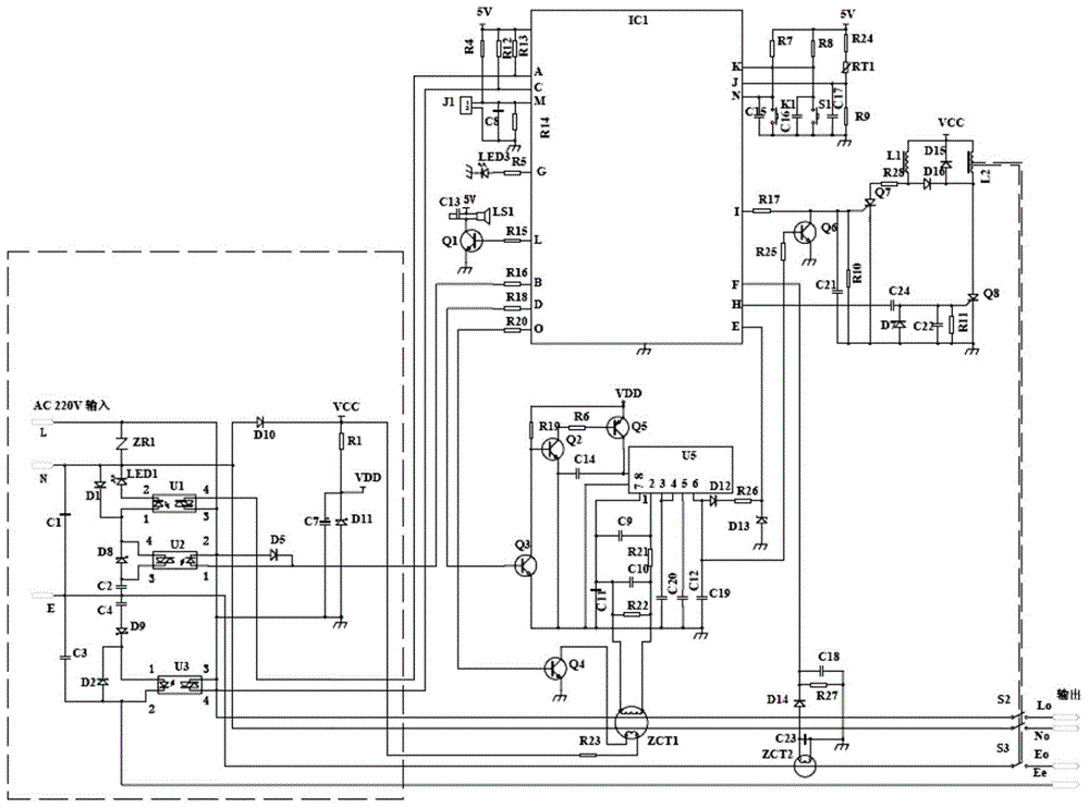
[0029] Such as figure 1 As shown, the present invention proposes an automatic power-on intelligent leakage protector, including a live wire L, a neutral wire N, a ground wire E, a tripping device, a rectifying and stabilizing circuit (rectifying diode D10), an amplifying circuit U5, and an amplifying circuit The zero-sequence transformer ZCT1 and the ground wire E transformer connected by U5 also include optocoupler U1, optocoupler U2, optocoupler U3 and single-chip microcomputer IC1; pin 2 of the optocoupler U1 is electrically connected to the neutral line N, and the optocoupler The pin 1 of U1 is connected to the pin 4 of the optocoupler U2, the pin 4 of the optocoupler U1 is connected to the A pin of the single-chip microcomputer IC1, and the pin 3 of the optocoupler U1 is connected to the pin 2 of the optocoupler U2; The pin 1 of the coupler U2 is connected to the B pin of the single-chip microcomputer IC1, and the pin 3 string C2 of the optocoupler U2 is electrically conn...

Embodiment 2

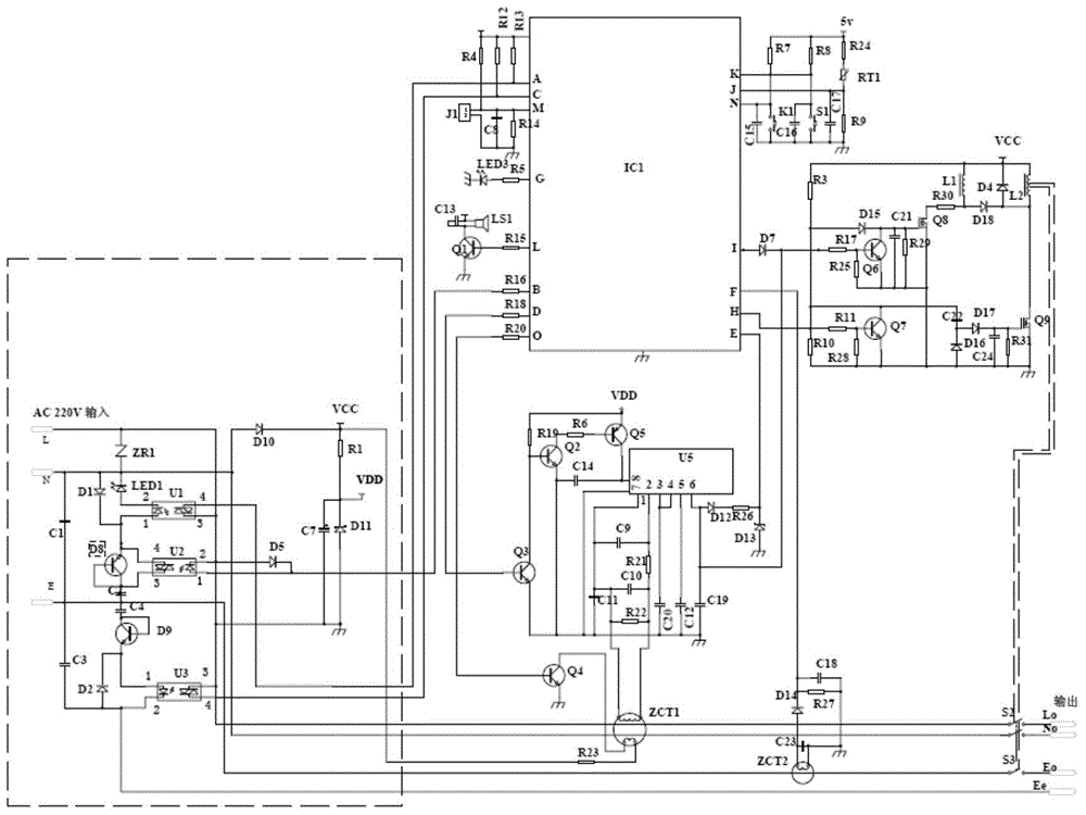
[0087] The implementation process and method of this embodiment and Embodiment 1 are basically the same, the difference is:

[0088] The regulator tubes D8 and D9 in the first embodiment are replaced by triodes D8 and D9; the silicon controlled rectifiers Q7 and Q8 can be replaced by field effect transistors Q8 and Q9, and their peripheral circuits are appropriately modified. Circuit schematic diagram see figure 2 .

Embodiment 3

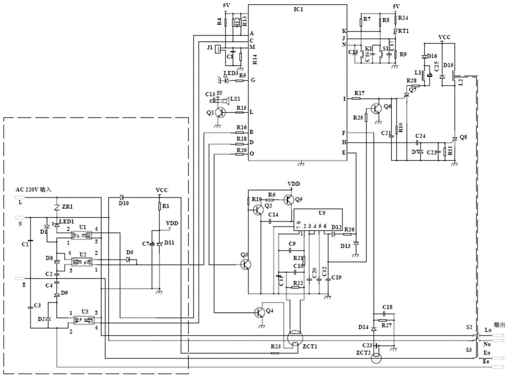
[0090] The implementation process and method of this embodiment and Embodiment 1 are basically the same, the difference is:

[0091] The diode D16 is connected in series with the sustaining coil L1, and an energy storage capacitor C25 is connected in parallel with the sustaining coil L1 to provide stable energy for the sustaining coil L1 and prevent the sustaining coil L1 from generating noise. Refer to the specific circuit schematic diagram image 3 .


PUM


Abstract

The invention discloses an automatic power-on intelligent-type electric leakage protector, and the protector comprises a live line, a zero line, a ground line, a wall body line, a tripper, a rectification voltage-stabilizing circuit, an amplification circuit, a zero-sequence mutual inductor connected with the amplification circuit, and a ground line mutual inductor connected with the amplification circuit. The protector also comprises an optical coupler U1, an optical coupler U2, an optical coupler U3, and a single-chip microcomputer IC1. The protector irons out the defects of all conventional electric leakage protectors and designs with potential safety hazards, is an omnibearing protection type electric leakage protector which integrated all functions into one body, and is intelligent, safe and reliable. The protection achieves the cut-off of power after coming out from water, achieves a use effect of water-electricity isolation, and has no potential safety hazards. The protector overcomes all the abnormalities caused by live-line and wiring errors of the ground line, and a system can carry out effective recognition detection and control.

Description

technical field [0001] The invention relates to the technical field of electricity safety protection, in particular to an automatic power-on intelligent leakage protector. Background technique [0002] The protection function of the leakage protector is based on the premise that the power supply is normal, and the ground wire is abnormally charged or the load is leaking to provide the protection function of cutting off the load power supply circuit. Because users generally use the socket switch to cut off the power supply of the leakage protector. The purpose of energy saving has been achieved by stopping the machine. Because of this, if the leakage protector loses its working power, if the ground wire is abnormally charged at this time, the leakage protector will not trip and cause an electric shock. And so on, poor contact with the socket is also equivalent to turning off the power supply of the leakage protector, which seriously affects personal safety hazards. Contents...

Claims


Application Information

Patent Timeline
IPC IPC(8): H02H3/32H02H3/28H02H3/04H02H5/04
Inventor 钱加灿
Owner YUYAO JIARONG ELECTRONICS & ELECTRIC APPLIANCE CO LTD
Why Eureka
Try Eureka