Stilt-type welding method for combination components

A technology of combining components and welding methods, applied in welding equipment, welding equipment, manufacturing tools, etc., can solve the problems of waste of manpower, material and financial resources, waste of tin materials, hidden danger of false welding, etc., to improve the pass rate, save manpower, improve performance effect

Inactive Publication Date: 2015-09-02
惠州联顺电子有限公司
View PDF0 Cites 0 Cited by
  • Summary
  • Abstract
  • Description
  • Claims
  • Application Information

AI Technical Summary

Problems solved by technology

[0003] The above seven steps are indispensable, but there are serious deficiencies in the above process, as follows: 1. In step 2, since the powder is scraped with a blade, the resin (powder) on the head of the resistance lead is easily scraped off. Causes damage to the surface of the lead wire and electrode, and the manual operation of the blade also poses a safety hazard to the human body, and the work efficiency is extremely low
2. In step 3, soldering can only be done by stacking tin to create "tin bumps", which not only wastes a lot of tin material; but also adds a blade to scrape off the tin slag remaining on the surface of the resistance ceramic chip during the "stacking tin" process, which is Further lead to the generation of step 4, which greatly wastes manpower, material resources and financial resources
3. In step 5, manual soldering is not only inefficient, but also varies in position, pitch, and length of leads, and there are hidden dangers of virtual soldering. Moreover, the position, spacing, and shape vary from person to person, and are not standardized and uniform, and the appearance is poor.
4. In step 6, the process of applying yellow glue will not only increase the labor and material costs of "yellow glue", but also cause pinhole hidden dangers in the subsequent painting after yellow glue is applied; it is easy to cause scrapped products after painting
5. In step 7, secondary coating and curing, this process causes a great waste of labor costs, electric energy, and tool usage
[0004] As mentioned above, the combination method of this temperature fuse and varistor is seriously unacceptable, therefore, it is necessary to invent a new method to solve the above problems

Method used


Image

  • Stilt-type welding method for combination components
  • Stilt-type welding method for combination components
  • Stilt-type welding method for combination components

Examples


Embodiment Construction

[0021] The following will clearly and completely describe the technical solutions in the embodiments of the present invention with reference to the accompanying drawings in the embodiments of the present invention. Obviously, the described embodiments are only some, not all, embodiments of the present invention. Based on the embodiments of the present invention, all other embodiments obtained by persons of ordinary skill in the art without making creative efforts belong to the protection scope of the present invention.

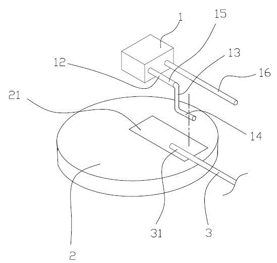
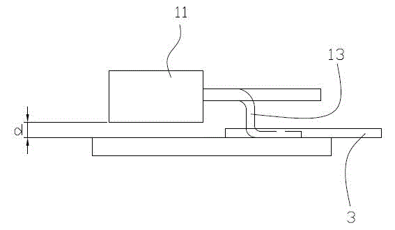
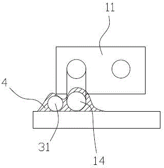
[0022] Such as Figure 1 to Figure 4 , the embodiment of the present invention provides a stilt-type welding method for combined components, which includes: a thermal fuse 1, a piezoresistor 2, a lead wire 3, a tin paste 4, and the piezoresistor 2 passes through a large When the current flows, a large amount of charge accumulates on the surface of the varistor 2 (ceramic sheet), and the heat generated by it will be transferred to the thermal fuse 1, and the th...


PUM


Abstract

The invention provides a stilt-type welding method for combination components. The method comprises bending and forming a first welding portion of a temperature fuse, arranging the first welding portion and a welding portion in the same plane to be welded, and packing. Compared with the present technology, five processes such as bottoming, powder scraping, tin heaping, residue scraping and secondary packing can be omitted. On the premise that a combination component work at the normal temperature and the temperature fuse cannot be burnout, the above processes are designed, the method is easy to operate, manpower, material resources and financial resources can be greatly saved, the performance of the product can be raised while the qualified rate of the product is raised, so the method is suitable for mass production and mechanical work.

Description

technical field [0001] The invention relates to a stilt type welding method for combined elements. Background technique [0002] The "temperature-controlled varistor" currently used in the market is also called "temperature fuse varistor" (referred to as "fuse resistance"). After being soldered together, they are packaged into a combined component. The varistor is a ceramic material, which has the characteristics of high temperature resistance, and the materials that make up the thermal fuse are low-temperature fusing materials and organic materials. If the temperature is too high, it is easy to cause the thermal fuse to burn out, and it is easy to cause the composite component to be scrapped. The existing combination (and welding) process adopts the "stacking" assembly process (that is, the fuse is assembled on the ceramic chip). Dip-coat a thin layer of resin (called "priming") on the resistance porcelain of the sensitive resistor, so that there is a heat insulation laye...

Claims


Application Information

Patent Timeline
Patent Type & Authority Applications(China)
IPC IPC(8): B23K31/00
CPCB23K31/02B23K1/00B23K1/20B23K31/00B23K2101/36
Inventor 马惠民
Owner 惠州联顺电子有限公司
Why Eureka
Try Eureka