Hydraulic retarder control system and control method

A hydraulic retarder and control system technology, applied in hydraulic brakes, brake types, mechanical equipment, etc., can solve the problems of brake lining wear, threatening driving safety, shortening brake life, etc., achieving high reliability, Easy to operate, compact effect

Inactive Publication Date: 2015-09-02
林会明
View PDF7 Cites 13 Cited by
  • Summary
  • Abstract
  • Description
  • Claims
  • Application Information

AI Technical Summary

Problems solved by technology

At such a high temperature, not only the braking ability is reduced, but also the brake drum is easily cracked, and the brake lining is seriously worn or burned.
Resulting in reduced brake life, early damage, increased maintenance costs, and even threats to driving safety
Advanced disc brakes are light in weight, good in performance, and low in maintenance costs. However, due to the small friction area, the thermal load generated by the huge kinetic energy during braking makes the surface temperature higher than that of drum brakes, and the wear is serious, which also cannot meet the requirements. Requirements for continuous braking on slope roads and high-speed strong braking

Method used


Image

  • Hydraulic retarder control system and control method

Examples


Embodiment Construction

[0023] The specific embodiments of the present invention will be further described below in conjunction with the drawings.

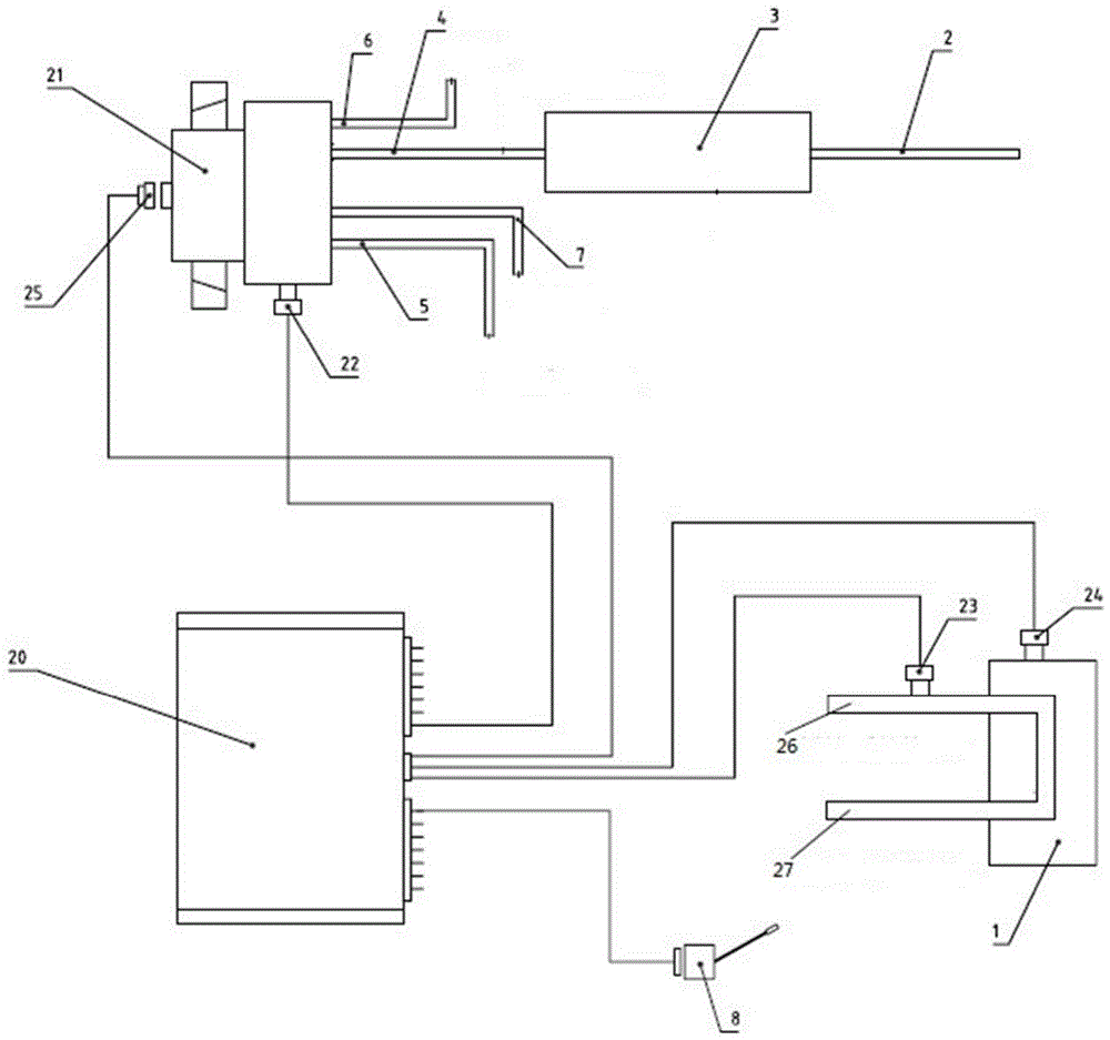
[0024] The control system of the hydraulic retarder includes an electromagnetic directional valve 21, a hydraulic retarder step switch 8, a control box 20, a compressed air pipeline, a vehicle auxiliary load air chamber 3, and a heat exchanger 1; the control box 20 is connected to the liquid The step switch 8 of the force retarder, the step switch 8 provides a working signal to the control box 20; the electromagnetic directional valve 21 is connected to the control box 20 through the electromagnetic directional valve current connection 25, and the control box 20 is connected to the electromagnetic directional valve 21 issues a control command; the electromagnetic reversing valve 21 is connected to the compressed air pipeline.

[0025] The compressed air pipeline includes a first compressed air pipeline 4 connected to the vehicle auxiliary load air chamber 3 a...


PUM


Abstract

The invention discloses a hydraulic retarder control system and a control method. The control system comprises a magnetic exchange valve controlling a hydraulic retarder. The control system further comprises a hydraulic retarder stepping switch, a control box, a compressed air pipeline, a vehicle auxiliary loading air chamber and a heat exchanger. The control box is connected to the stepping switch of the hydraulic retarder, and the stepping switch provides working signals for the control box. The magnetic exchange valve is connected to the control box, and the control box sends control commands to the magnetic exchange valve. The magnetic exchange valve is connected to the compressed air pipeline. By employing the hydraulic retarder control system, oil can be rapidly charged and discharged for the hydraulic retarder, and the oil charging rate of the hydraulic retarder can be continuously adjusted according to retarding requirements, thereby bringing high reliability and convenient control.

Description

Technical field [0001] The present invention relates to the field of automobile parts and automobile manufacturing, in particular to the field of auxiliary brakes for automobiles-hydraulic retarders for automobiles. technical background [0002] The safety of automobiles has always been important, especially in today's booming automobile transportation industry, which requires vehicles to have higher operating efficiency. Therefore, the quality of vehicles increases, the speed of vehicles increases, and the kinetic energy of vehicles increases exponentially. The braking ability of the service brake cannot be improved simultaneously due to the limitation of many factors. When the brake is subjected to long-term continuous braking and high-speed braking on a long slope, the brake is subjected to a strong load of huge kinetic energy transformed into heat energy, brake linings and brake drums The temperature can be as high as 1000°C. At such a high temperature, not only the braking ...

Claims


Application Information

Patent Timeline
Patent Type & Authority Applications(China)
IPC IPC(8): B60T10/02
CPCB60T10/02
Inventor 林会明王际成
Owner 林会明
Why Eureka
Try Eureka