Method and device for pyrolytic carbonizing treatment of sludge

A technology of pyrolysis carbonization and treatment method, which is applied in the direction of dehydration/drying/thickened sludge treatment, pyrolysis treatment sludge, special form of carbonization, etc., and can solve the problem of heat supply and heat utilization of auxiliary combustion chambers and combustion chambers Low cost, complex overall process and corresponding structure, and large equipment occupation area, etc., to achieve the effect of simple structure, reducing the incidence of equipment failure, and ensuring normal operation

Active Publication Date: 2015-09-02
ZHE JIANG ECO ENVIRONMENTAL TECH CO LTD
View PDF3 Cites 24 Cited by
  • Summary
  • Abstract
  • Description
  • Claims
  • Application Information

AI Technical Summary

Problems solved by technology

[0004] In the actual use process, according to the applicant's report, this set of equipment can complete the drying and carbonization of sludge well, but it has certain problems: although the external heating type drying furnace and external heating type carbonization furnace can Adjust and control the temperature in the drying device and the carbonization device through auxiliary heating, but they need to be configured as follows figure 1 The above-mentioned auxiliary combustion chambers are equipped with corresponding burners, and the overall process and corresponding structure of the equipment are complicated. Low, the equipment occupies a large area and the production cost is high

Method used


Image

  • Method and device for pyrolytic carbonizing treatment of sludge
  • Method and device for pyrolytic carbonizing treatment of sludge
  • Method and device for pyrolytic carbonizing treatment of sludge

Examples


Embodiment 1

[0055] Figure 5 It is a process flow diagram of the sludge pyrolysis carbonization treatment method in Embodiment 1. Such as Figure 5 As shown, a sludge pyrolysis carbonization treatment method, including heat supply, pre-treatment, carbonization treatment, gas treatment and gas utilization,

[0056] (a) Heating part: a burner is set, and the flame port of the burner is passed into a combustion chamber to obtain high-temperature flue gas;

[0057] (b) Pre-treatment part: put the sludge into the pre-treatment chamber, and the high-temperature flue gas introduced into the heating part is heated by an external heating jacket to heat the sludge in the pre-treatment chamber. The temperature is 500-700°C, and the pre-treatment room is heated to 100-250°C;

[0058] (c) Carbonization treatment part: send the pre-treated sludge into the carbonization treatment room, introduce high-temperature flue gas from the heating part, and use the external heating jacket to heat the sludge in...

Embodiment 2

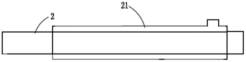
[0066] Figure 6 It is a schematic diagram of the overall structure of the sludge pyrolysis carbonization treatment device in Example 2. Such as Figure 6 As shown, a sludge pyrolysis carbonization treatment device includes a combustion chamber 1, a pre-treatment unit, a carbonization treatment unit, a gas treatment unit and a gas utilization unit, and the combustion chamber 1 is provided with a burner 1a; as image 3 As shown, the pre-processing unit is an external heat dryer 2, the dryer 2 is provided with a dryer jacket 21, and the dryer jacket 21 passes through the flue gas delivery pipeline 4 and the high-temperature flue gas outlet of the combustion chamber 1 1a is the same; if Figure 4 As shown, the carbonization treatment unit is an external heating type carbonization furnace 3, the carbonization furnace 3 is provided with a carbonization furnace jacket 31, and the carbonization furnace jacket 31 passes through the flue gas delivery pipeline 4 and the high-temperatu...


PUM


Abstract

The invention relates to a method for pyrolytic carbonizing treatment of sludge. The method comprises: a heat supplying portion: arranging a combustor, and introducing a flaming port of the combustor into a combustion chamber to obtain high-temperature flue gas; a pre-treating portion: putting the sludge into a pre-treating chamber, and introducing the high-temperature flue gas of the heat supplying portion so as to heat the sludge to the temperature of 100-250 DEG C; a carbonizing treatment portion: feeding the pre-treated sludge into a carbonizing treatment chamber, and introducing the high-temperature flue gas of the heat supplying portion so as to heat the pre-treated sludge to the temperature of 450-650 DEG C; a gas treating portion: separately collecting gas-phase products generated from pre-treating and carbonizing treatment, and condensing the collected gas-phase products correspondingly by adopting a water spraying manner, so as to respectively obtain first oil, first noncondensable gas, second oil and second noncondensable gas; and a gas utilizing portion: introducing the second noncondensable gas into the combustion chamber of the heat supplying portion for combustion. The invention also provides a device for implementing the method. The method and the device have the advantages of simplified process, small equipment quantity, stability and reliability in operation, energy saving and environmental protection, high oil recovery ratio, and the like.

Description

Technical field: [0001] The invention belongs to the technical field of sludge treatment, and more specifically relates to a sludge pyrolysis carbonization treatment method and device. Background technique: [0002] In recent years, the output of sewage and sludge-based waste produced in the process of oil exploitation has been increasing continuously, and its composition is complex. Due to the high moisture content and large volume of sludge, it has caused difficulties in the recycling of sewage and sludge, and Its storage or landfill needs to occupy a large area of ​​land, which is easy to pollute the environment. Among them, the oily sludge contains a large amount of petroleum hydrocarbons, and the tail gas generated during the pyrolysis and carbonization process under the condition of oxygen isolation mostly contains acid gases (such as HCL, SOX, HF, etc.), nitrogen oxides (Nox), dioxins (PCDDS / PCDFS) and heavy metals (Hg, Pb) and other toxic gases. If these toxic gases ...

Claims


Application Information

Patent Timeline
Patent Type & Authority Applications(China)
IPC IPC(8): C02F11/10C02F11/12C10B53/00C10B57/10
Inventor 车磊
Owner ZHE JIANG ECO ENVIRONMENTAL TECH CO LTD
Why Eureka
Try Eureka