Filled-type gas chromatographic column and preparation method thereof

A gas chromatographic column and packed technology, which is applied in the field of packed gas chromatographic column and its preparation, can solve the problems of limited sample capacity, easy breaking of the column, and limited application, so as to improve the application range, reduce the system volume, and increase the sample size. The effect of capacity

Active Publication Date: 2015-09-02
INST OF ELECTRONICS CHINESE ACAD OF SCI
View PDF8 Cites 13 Cited by
  • Summary
  • Abstract
  • Description
  • Claims
  • Application Information

AI Technical Summary

Problems solved by technology

[0005] But, there is certain defective in above-mentioned micro gas chromatographic column
First, the method of designing microcolumns in the channel can increase the surface area of ​​the channel, but it also limits the depth of the channel. From the above figure, it can be found that due to the limitation of processing technology, the greater the depth of the chromatographic channel, the greater the depth of the channel. The diameter of the micro-pillar becomes thinner and thinner. When the channel reaches 200 microns, it is close to the limit of the existence of the column. If it is deeper, the column will be easily broken; secondly, the fixed phase film (Al 2 o 3 ) is to coat the stationary phase on the surface of the channel and column by atomic deposition technology. The thickness of the stationary phase film is very limited, only 10nm, which is far smaller than the traditional range of 200nm-20000nm, which greatly limits the sample capacity and is difficult to apply Separation of complex mixtures; thirdly, the stationary phase is coated by atomic deposition technology, and the types of stationary phase materials that can be coated are very limited, which greatly limits its application in a wider range of fields

Method used


Image

  • Filled-type gas chromatographic column and preparation method thereof
  • Filled-type gas chromatographic column and preparation method thereof
  • Filled-type gas chromatographic column and preparation method thereof

Examples


Embodiment Construction

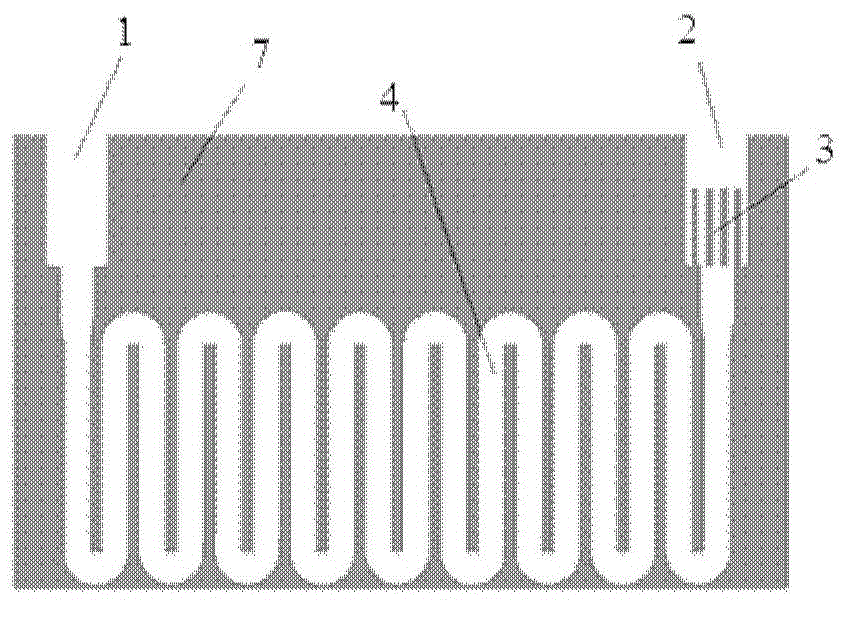
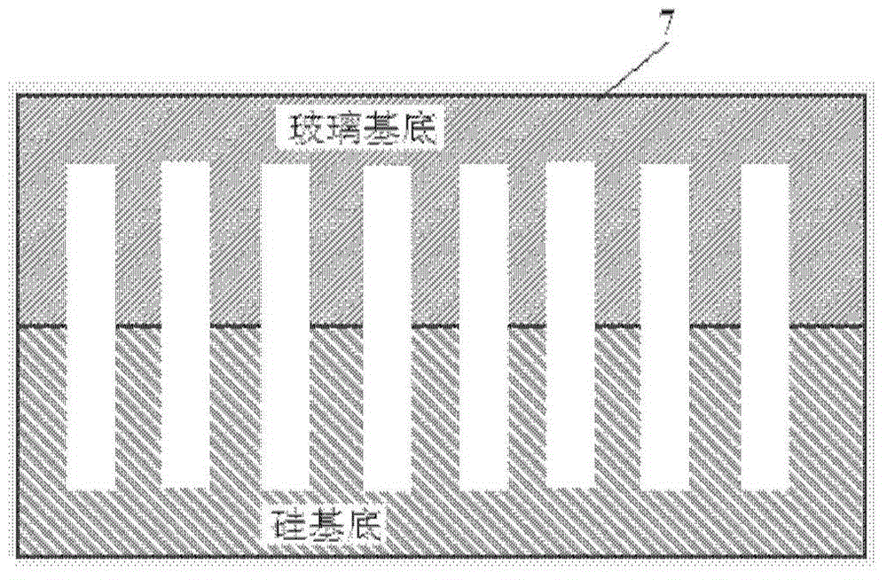
[0030] In order to make the object, technical solution and advantages of the present invention clearer, the present invention will be described in further detail below in conjunction with specific embodiments and with reference to the accompanying drawings. It should be noted that, in the drawings or descriptions of the specification, similar or identical parts all use the same figure numbers. Implementations not shown or described in the accompanying drawings are forms known to those of ordinary skill in the art. Additionally, while illustrations of parameters including particular values ​​may be provided herein, it should be understood that the parameters need not be exactly equal to the corresponding values, but rather may approximate the corresponding values ​​within acceptable error margins or design constraints. The directional terms mentioned in the embodiments, such as "upper", "lower", "front", "rear", "left", "right", etc., are only referring to the directions of the...


PUM

PropertyMeasurementUnit
lengthaaaaaaaaaa
depthaaaaaaaaaa
widthaaaaaaaaaa

Abstract

The invention provides a filled-type gas chromatographic column. The filled-type gas chromatographic column comprises a first substrate, a second substrate and a chromatographic packing. Micro-channels are processed on the surface of the first substrate. Micro-channels are processed on the surface of the second substrate. The position of the micro-channels on the surface of the second substrate is corresponding to the position of the micro-channels on the surface of the first substrate. After the first substrate and the second substrate are combined tightly, the micro-channels on first substrate and the micro-channels on second substrate together form chromatographic column micro-channels. The chromatographic packing is filled in the chromatographic column micro-channels. The filled-type gas chromatographic column is formed by mutual bonding of the two substrates. As the chromatographic column micro-channels are formed by the micro-channels on the surfaces of the two substrates, limit of corresponding dimensions is broken through, length is larger, and reliability is higher. The invention also provides a preparation method of the above filled-type gas chromatographic column.

Description

technical field [0001] The invention relates to the technical field of chromatography detection, in particular to a packed gas chromatography column and a preparation method thereof. Background technique [0002] For environmental air quality monitoring, environmental air quality monitoring in equipment, smart grid and oil exploration and other fields to pollute air (mainly CO, CO 2 , NO 2 , SO 2 、H 2 S, C1~C6 and other low-carbon hydrocarbons, etc.) are urgently needed for rapid and efficient separation and detection. The existing technology urgently needs micro gas chromatography columns to achieve fast and efficient separation of low-carbon compounds and permanent gases. [0003] And currently for CO, CO 2 , SO 2 , NO 2 、H 2 S, C1-C6 and other low-carbon hydrocarbons separation technologies and methods mostly use traditional capillary chromatographic columns and packed columns. These traditional chromatographic columns are not suitable for on-site monitoring due to...

Claims


Application Information

Patent Timeline
Patent Type & Authority Applications(China)
IPC IPC(8): G01N30/60
Inventor 孙建海崔大付张璐璐陈兴
Owner INST OF ELECTRONICS CHINESE ACAD OF SCI
Why Eureka
Try Eureka