Flame holder and ground gas turbine combustion chamber with same

A flame stabilizer and combustion chamber technology, applied in combustion chambers, continuous combustion chambers, combustion methods, etc., can solve the problems of wasting combustion chamber space, increasing pollutants, increasing gas residence time, etc., achieving full combustion and reducing residence time. , compact structure

Active Publication Date: 2015-09-09
ELECTRIC POWER RES INST OF GUANGDONG POWER GRID +1
View PDF13 Cites 9 Cited by
  • Summary
  • Abstract
  • Description
  • Claims
  • Application Information

AI Technical Summary

Problems solved by technology

However, this design makes it downstream for a considerable distance, because the air velocity is too high to catch fire, which wastes the combustion chamber space, increases the residence time of the gas in the combustion chamber, and increases the generation of pollutants.

Method used


Image

  • Flame holder and ground gas turbine combustion chamber with same
  • Flame holder and ground gas turbine combustion chamber with same
  • Flame holder and ground gas turbine combustion chamber with same

Examples


Embodiment Construction

[0024] Below in conjunction with accompanying drawing and embodiment the present invention will be described in further detail:

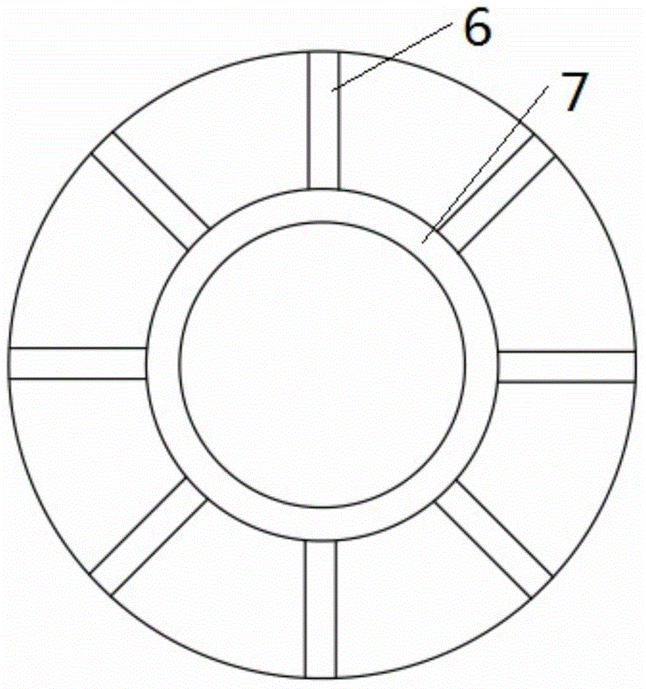
[0025] Such as Figure 2~4 As shown, the flame stabilizer of this embodiment includes a central ring 7, eight radial struts 6 (the number of radial struts corresponds to the number of main swirlers in the combustion chamber) and a connecting ring. The central ring 7 is arranged in the middle of the connecting ring in parallel, and eight radial struts 6 are evenly fixed on the outer ring surface of the central ring 7 along the radial direction, and the free ends are connected with the inner ring surface of the connecting ring.

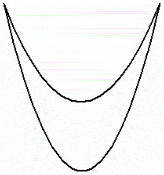
[0026] Both the ring body of the central ring 7 and the radial struts 6 are formed by components of a groove-like structure. Such as image 3 As shown, the member of the trough structure is composed of two upper and lower arc-shaped surfaces, the two sides of the two arc-shaped surfaces are overlapped together, and a cavity...


PUM


Abstract

The invention discloses a flame holder and a ground gas turbine combustion chamber with the same. The flame holder comprises a central ring and a plurality of radial struts fixed on the outer circular face of the central ring along the radial direction uniformly. A ring body of the central ring and the radial struts are formed by members in groove structures, and groove opening directions of the central ring and the radial struts are identical. Gas flow channels are formed in the members in groove structures and are communicated with the outside through a plurality of gas spray holes in the bottoms of the grooves. The gas flow channel in the central ring and the gas flow channels in the radial struts are communicated to form a gas flow cavity with the shape corresponding to the shape of the flame holder. By means of the flame holder, fuel gas can be burnt stably on the flame holder even under the impact of high-speed gas flows.

Description

technical field [0001] The invention relates to the field of gas turbines, in particular to a flame stabilizer, and also to a ground gas turbine combustion chamber equipped with the flame stabilizer. Background technique [0002] With the general strengthening of people's awareness of environmental protection, countries all over the world have formulated environmental protection regulations (laws) accordingly, and put forward increasingly strict limits on the pollutant emissions of various combustion equipment and power plants. Although there were international legal regulations during the 1980s and 1990s, many countries made sulfur dioxide (SO 2 ) emissions are significantly reduced, but nitrogen oxides (NO X ) is relatively small. NO X It has increasingly become the key to pollution emission control in various countries, because it is the key pollutant of compound pollution and will bring a series of environmental problems. Dry low NOx (DLN) combustion technology is ba...

Claims


Application Information

Patent Timeline
Patent Type & Authority Applications(China)
IPC IPC(8): F23R3/18F23R3/42
Inventor 刘石邓小文尹洪冯永新田丰邢力张群
Owner ELECTRIC POWER RES INST OF GUANGDONG POWER GRID
Why Eureka
Try Eureka