Two-phase flow liquid distributor

A liquid separator and phase flow technology, applied in the field of compressors, can solve the problems of large drop in liquid separation performance, complex process flow, easy welding and blocking, etc.

Inactive Publication Date: 2015-09-09
SHANGHAI JIAO TONG UNIV +1
View PDF6 Cites 8 Cited by
  • Summary
  • Abstract
  • Description
  • Claims
  • Application Information

AI Technical Summary

Problems solved by technology

However, both of these two liquid separators have disadvantages: the pressure drop type liquid separator uses the method of throttling the inflowing two-phase flow and increasing the turbulence to mix the gas-liquid two-phase evenly, so that the liquid separation is uniform, but Because there is a throttling ring in this type of liquid separator, the pressure drop is large and turbulent noise will be generated; the Venturi type liquid separator reduces turbulence through the internal tapering and expanding structure, but increases the flow rate of the refrigerant to make the gas-liquid two-phase The flow is evenly mixed, so as to achieve the purpose of uniform distribution, but its internal processing accuracy is high, the process is complicated and the cost is high; at the same time, when the capillary tube is welded to each channel of the distributor, the channel diameter is small. Solder plugging, reducing the process reliability of the product
However, due to the limitation of the diameter of the single cylinder in this prior art, the distance between the outlet capillaries is similar. Therefore, when the inlet pipe of the liquid separator is bent, the liquid separation performance drops greatly.

Method used


Image

  • Two-phase flow liquid distributor
  • Two-phase flow liquid distributor
  • Two-phase flow liquid distributor

Examples


Embodiment 1

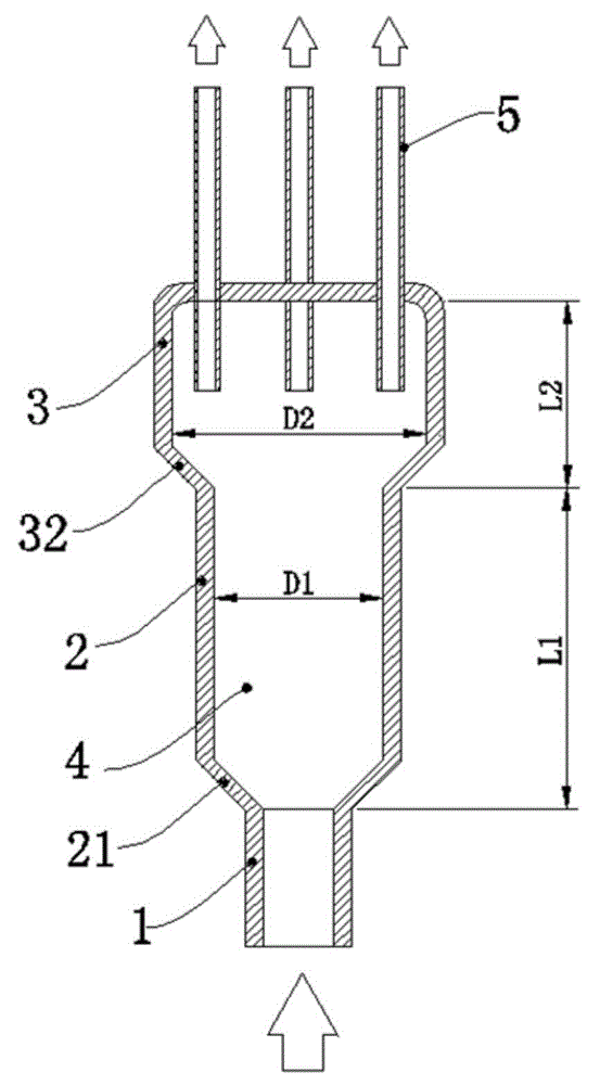
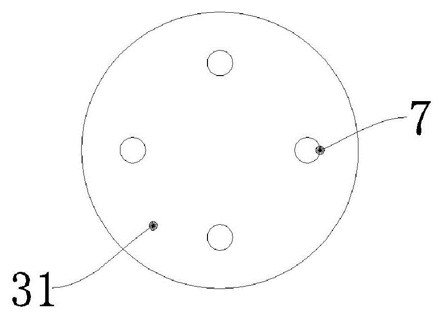
[0024] Such as figure 1 and figure 2 As shown, this embodiment includes: an inlet pipe 1, a front cylinder body 2, a rear cylinder body 3 and a branch pipe 5, wherein: the inlet pipe 1, the front cylinder body 2 and the rear cylinder body 3 are connected in sequence and the cross sections are Circular structure, the inside of the front cylinder 2 and the rear cylinder 3 forms a hollow chamber 4, and the top 31 of the rear cylinder 3 is evenly spaced with a number of liquid separation holes 5 communicating with the hollow chamber 4, and each liquid separation hole 5 is provided with a branch pipe 7;

[0025] The inner diameters of the inlet pipe 1, the front cylinder body 2 and the rear cylinder body 3 increase sequentially.

[0026] The relationship between the length L1 and inner diameter D1 of the front cylinder 2 and the length L2 and inner diameter D2 of the rear cylinder 3 satisfies: 1.5 ≤ ( L ...

Embodiment 2

[0039] Such as Figure 6 As shown, the inside of the front cylinder body 2 is provided with a cylindrical built-in filter screen. The cross section of the built-in filter screen is trapezoidal, and its bottom edge is fixed on the groove structure provided inside the front cylinder body 2 .


PUM


Abstract

The invention discloses a two-phase flow liquid distributor in the field of compressors, which comprises an inlet pipe, a front barrel, a rear barrel and branch pipes, wherein the inlet pipe, the front barrel and the rear barrel of which cross sections are of round structures are communicated in sequence and are coaxially arranged; the inside of the front barrel and the inside of the rear barrel form a hollow chamber; a plurality of liquid distributing holes which are communicated with the hollow chamber are uniformly formed in the top of the rear barrel at intervals in an equal angle; and one branch pipe is arranged on each liquid distributing hole. The invention has the advantages that the pressure drop can be reduced; noises are reduced; and the structure is simplified.

Description

technical field [0001] The invention relates to a device in the field of compressors, in particular to a two-phase flow separator. Background technique [0002] The distributor, also known as the liquid separator, is used to equally distribute the refrigerant two-phase fluid from the expansion mechanism to each heat exchange flow path of the evaporator, so that the heat exchange area of ​​the heat exchanger can be fully utilized. A distributor that evenly distributes refrigerant can improve the overall heat transfer performance of the evaporator, thereby improving the working performance of the entire refrigeration system. In the past, the traditional refrigerant distributors were commonly seen in the market as pressure-drop type and Venturi type. These two distributors are equipped with orifices or nozzles inside to increase the acceleration of the refrigerant two-phase fluid and reduce the deviation of each heat exchange circuit. However, both of these two liquid separat...

Claims


Application Information

Patent Timeline
Patent Type & Authority Applications(China)
IPC IPC(8): F25B41/00F25B41/42
CPCF25B41/00
Inventor 陈江平张驰王利孙西辉马小魁
Owner SHANGHAI JIAO TONG UNIV
Why Eureka
Try Eureka