Method for replacing sintering machine air box chutes and air box girders

A sintering machine and bellows technology, which is applied to furnace types, furnaces, lighting and heating equipment, etc., can solve the problems of low construction efficiency, large replacement workload, long construction time, etc., so as to shorten construction time, reduce labor intensity, and improve The effect of safety features

Active Publication Date: 2015-09-09
MCC BAOSTEEL TECH SERVICE
View PDF7 Cites 4 Cited by
  • Summary
  • Abstract
  • Description
  • Claims
  • Application Information

AI Technical Summary

Problems solved by technology

When replacing the bellows chute and bellows girder, the bellows chute and bellows girder outside the ignition furnace and holding furnace area of ​​the sintering machine should be reversed and disassembled by cranes and chain hoists. The workload of all replacement is heavy, the efficiency of dismantling and installation is relatively low, and a long construction time is required
[0005] In addition, the bellows chute and bellows girder inside the ignition furnace and holding furnace cannot be transported and disassembled by the crane, which only requires manpower, material resources and construction time. The adjustment of the bellows girder is extremely unfavorable, and the construction efficiency is extremely low; it is best to use a hand chain hoist to transport one by one to the designated location and then install and adjust it, which requires a lot of work. Relying on manual chain hoists for unloading, low safety factor for disassembly and assembly, it is impossible to ensure the safety of workers accurately and effectively

Method used


Image

  • Method for replacing sintering machine air box chutes and air box girders
  • Method for replacing sintering machine air box chutes and air box girders
  • Method for replacing sintering machine air box chutes and air box girders

Examples


Embodiment Construction

[0037] The following specific examples illustrate the implementation of the present invention. Those familiar with the technology can easily understand other advantages and effects of the present invention from the content disclosed in this specification.

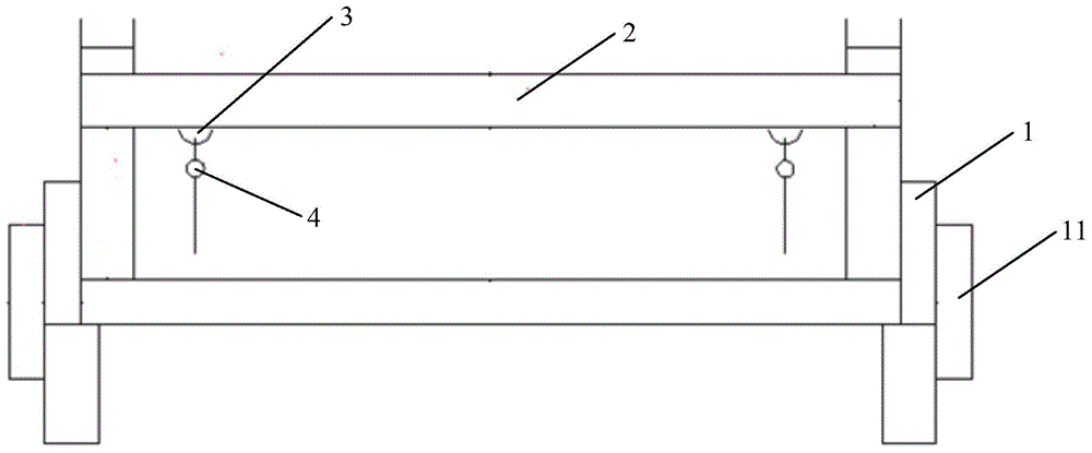
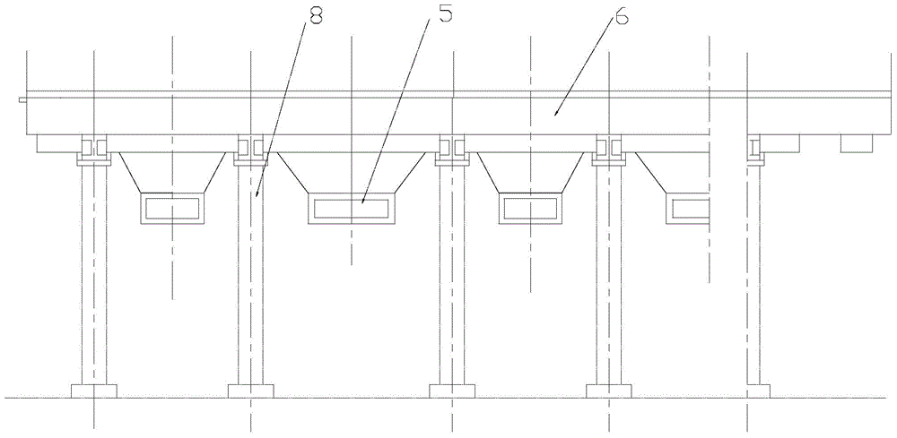
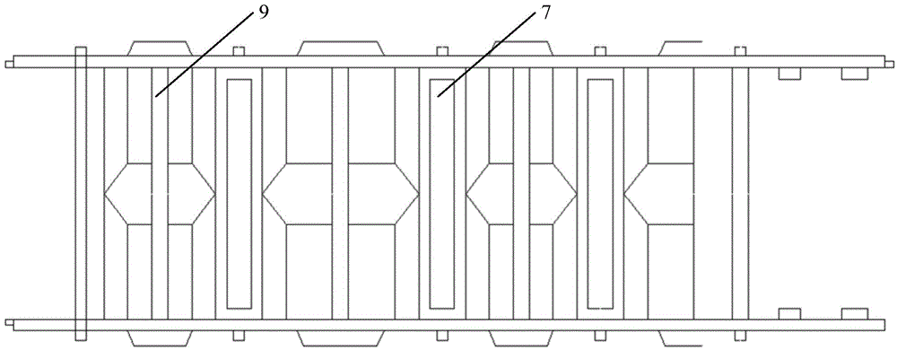
[0038] See Figure 1 to Figure 3 . It should be noted that the structures, proportions, sizes, etc. shown in the accompanying drawings in this specification are only used to match the content disclosed in the specification for people familiar with this technology to understand and read, and are not intended to limit the implementation of the present invention Limited conditions, so it has no technical significance. Any structural modification, proportional relationship change or size adjustment should still fall under the present invention without affecting the effects and objectives that can be achieved by the present invention. The disclosed technical content must be within the scope of coverage. At the same time, the term...


PUM


Abstract

The invention provides a method for replacing sintering machine air box chutes and air box girders. The method includes the steps: manufacturing a hoisting tool; preassembling the air box girders; hanging the preassembled air box girders on the hoisting tool, and conveying the air box girders to the inside of an ignition furnace for mounting when the air box girders are mounted inside the ignition furnace; transporting the preassembled air box girders to a framework of a sintering machine by a crane for mounting when the air box girders are mounted outside the ignition furnace; mounting the air box chutes below the air box girders. The hoisting tool comprises two groups of supporting rods which are arranged on two trolleys respectively, the height of each supporting rod is lower than the scale height of the ignition furnace or a heat preserving furnace, a square frame is arranged at the top ends of two groups of supporting rods, and a lifting device is arranged on the square frame. The method can greatly shorten construction time and effectively solves the problem of difficulty in dismounting and mounting an air box and air box girders in the ignition furnace and the heat preserving furnace, labor intensity is reduced, and working efficiency and safety are improved.

Description

Technical field [0001] The invention relates to the maintenance of a sintering machine; [0002] In particular, it relates to a method for replacing the wind box chute and the wind box beam of a sintering machine. Background technique [0003] The sintering machine uses a fan to draw air to make the sintered ore perform preliminary cooling. The ventilation channel between the sintering machine and the fan is composed of wind box, branch pipe, flue and other equipment. [0004] After the wind box chute and wind box beam of the sintering machine reach the service life, they need to be replaced. When replacing the wind box chute and wind box girder, the wind box chute and wind box girder outside the area of ​​the sintering machine ignition furnace and holding furnace are transported, disassembled, and disassembled with the cooperation of cranes and chain hoists. However, due to the wind box girder and wind flow process The total replacement workload is very large, the dismantling and ...

Claims


Application Information

Patent Timeline
Patent Type & Authority Applications(China)
IPC IPC(8): F27B21/08
Inventor 王科窦胜王志锋苍鸿顺
Owner MCC BAOSTEEL TECH SERVICE
Why Eureka
Try Eureka