Robot joint reducer test bed

A robot joint and reducer technology, applied in the field of transmission testing, can solve the problems of low degree of automation, poor adjustability, and few experimental items, and achieve the effects of reducing manual operation, reducing energy consumption and accurate data

Active Publication Date: 2015-09-09
HEFEI UNIV OF TECH +1
View PDF11 Cites 20 Cited by
  • Summary
  • Abstract
  • Description
  • Claims
  • Application Information

AI Technical Summary

Problems solved by technology

[0004] At present, a large number of test benches have been designed for different reducers and transmissions at home and abroad. However, there are mainly two types of test benches commonly used at present: one is the input motor-torque sensor-reducer-torque sensor-loading motor. The disadvantage of the test bench is high energy consumption, it is difficult to control the synchronous speed of the two motors, and the degree of automation is low; the other is the input motor-torque sensor-reducer-torque sensor-magnetic powder brake. The disadvantage of this test bench is high energy consumption, which can be Poor adjustment, few experimental items, low degree of automation
At the same time, the common characteristics of the existing reducer test benches are that the output torque is constant, and the output shaft has no radial force.
This is quite different from the actual working conditions of the robot joint reducer. If the existing test bench is used for testing, it cannot reflect the real operating characteristics of the robot joint reducer.

Method used


Image

  • Robot joint reducer test bed
  • Robot joint reducer test bed
  • Robot joint reducer test bed

Examples


Embodiment Construction

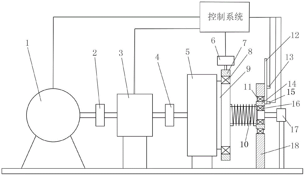
[0030] In this example, see figure 1 , a test bench for a robot joint reducer, comprising: a drive motor 1, a sensor 3, a tested robot joint reducer 5, a loader 6, an output disk 9, a torsion spring 10, a rotation angle device 12, a rotation angle disk 14, and an angle sensor 17. Support frame 18 and control system;

[0031] A sensor 3 is installed between the input end of the tested reducer 5 and the drive motor 1, the controllable steering drive motor 1 is connected to the sensor through the coupling 2, and the sensor 3 is connected to the input of the tested reducer 5 through the coupling 4 The sensor 3 can be a different type of sensor, so as to test different types of data and facilitate the testing of multiple items, and the output end of the tested reducer 5 is connected to the side end surface of the output disc 9 through the mounting hole on it. connected;

[0032] A fixed disk 7 is arranged on the outside of the output disk 9, and a loader 6 is arranged above the f...


PUM


Abstract

The invention discloses a robot joint reducer test bed. The robot joint reducer test bed is characterized by comprising a driving motor, a measured robot joint reducer, a loader, an output tray, a torsion spring, a turntable device, an angle sensor and a control system, the turntable device applies an initial turning angle on the torsion spring, the output tray applies torque to the measured reducer, the driving motor drives the measured reducer to rotate, the loader applies radial force on the measured reducer, and input and output test parameters of the measured reducer are respectively acquired by the aid of a sensor and the angle sensor. Real working conditions of the robot joint reducer can be simulated, experimental reliability is increased, energy consumption is reduced, and automatic control performance is improved.

Description

technical field [0001] The invention relates to the technical field of transmission testing, in particular to a robot joint reducer testing system. Background technique [0002] As one of the key technologies of the robot, the robot joint reducer has the characteristics of high rigidity, small hysteresis, high load, compact structure, small size, light weight, and high efficiency. In engineering practice, due to the manufacturing and installation errors of the parts, as well as the deformation, wear and sinking of the parts during use, the dynamic instability of the robot movement, the poor dynamic stiffness and the inability to return the difference will be caused. Control, etc., it is difficult to obtain high motion accuracy, and additional dynamic load is generated, which causes vibration and noise, and deteriorates the working condition of the robot. In the current study, experiment is the main way to study the above characteristics of the reducer. [0003] The experim...

Claims


Application Information

Patent Timeline
Patent Type & Authority Applications(China)
IPC IPC(8): G01M13/02
Inventor 黄康段松林高峰宋飞杨沁洪建
Owner HEFEI UNIV OF TECH
Why Eureka
Try Eureka