Automatic calibration simulation testing system for ECU stand
An automatic calibration and simulation test technology, which is applied in the direction of test/monitoring control system, general control system, electrical test/monitoring, etc., can solve the problems of shortening the calibration time and occupying bench resources, so as to shorten the calibration time and save the calibration cost Effect
- Summary
- Abstract
- Description
- Claims
- Application Information
AI Technical Summary
Problems solved by technology
Method used
Image
Examples
Embodiment 1
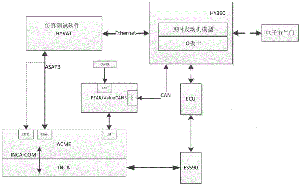
[0018] An ECU bench automatic calibration simulation test system, including engine controller ECU, calibration equipment ES590, calibration PC running calibration software INCA and automatic calibration software ACME, simulation system PC running simulation test software HYVAT, PeakCAN / ValueCAN3USBCAN communication Equipment, HY230 function test bench and electronic throttle, the automatic calibration software ACME interacts with the calibration software INCA through the virtual COM port; the simulation test software HYVAT simulates the ASAP3 slave node (RS232 or Ethernet), and interacts with the ASAP3 master node of the automatic calibration software ACME ;The calibration software INCA interacts with the engine controller ECU through the calibration device ES590; the automatic calibration software ACME interacts with the HY230 function test bench or other CAN devices through the PeakCAN / ValueCAN3USBCAN communication device; the simulation test software HYVAT interacts with the ...
Embodiment 2
[0022] The difference from Example 1 is that the simulation hardware platform adopts the real-time simulation system HY360, including multi-core industrial computer, real-time system RTPC, input and output IO board and engine model. The engine-related models (load model, exhaust temperature model, etc.) run on the real-time system RTPC of the real-time simulation system HY360. The real-time simulation system HY360 collects the drive output signals (fuel injection, ignition signals, etc.) of the engine controller ECU in real time through the IO input board. ), after the calculation of the engine model, the calculation result is output to the engine controller ECU through the IO output board, so as to complete the model of various sensor signals (crankshaft speed signal, water temperature signal, etc.). The rest works the same.
PUM
 Abstract
Description
Claims
Application Information
 - R&D
- Intellectual Property
- Life Sciences
- Materials
- Tech Scout
- Unparalleled Data Quality
- Higher Quality Content
- 60% Fewer Hallucinations
Browse by: Latest US Patents, China's latest patents, Technical Efficacy Thesaurus, Application Domain, Technology Topic, Popular Technical Reports.
© 2025 PatSnap. All rights reserved.Legal|Privacy policy|Modern Slavery Act Transparency Statement|Sitemap|About US| Contact US: help@patsnap.com


