Method for designing multi-path server QPI clamp based on converged infrastructure
A multi-channel server and design method technology, applied in the field of server motherboard design, can solve the problems of inability to realize the QPI full interconnection mode, inconvenience, etc., and achieve the effect of easy upgrade and upgrade switching, reducing wiring, and convenient switching.
- Summary
- Abstract
- Description
- Claims
- Application Information
AI Technical Summary
Problems solved by technology
Method used
Image
Examples
Embodiment 1
[0024] see figure 1 , is a schematic diagram of the QPI connection in the 2S QPI subcard, 2S means that there are 2 CPUs, and so on. For the case where one computing node has only 2 CPUs and the computing nodes are the same, the QPI subcard of the multi-channel server is installed on the motherboard computing node. When there is only one computing node, the shortest distance between the two CPU1 and CPU2 in the computing node QPI connection, indicated by the dotted line in the figure, CPU1 and CPU2 outside the computing node are interconnected through QPI, indicated by the black solid line in the figure. The uppermost side is the main computing node.
[0025] The QPI subcard contains a clock source chip to provide a clock reference for each computing node.
[0026] The QPI subcard also contains ID signals. The server system is equipped with BMC and FPGA. After the FPGA detects the ID signal of the QPI subcard, it will perform multi-channel timing control by default. Use the ...
Embodiment 2
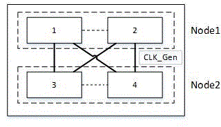
[0036] see figure 2 , is a schematic diagram of the QPI connection in the 4S QPI subcard. For the case where the computing node has only 2 CPUs and the computing nodes are the same, the multi-channel server QPI subcard is installed on the mainboard computing node. There are 2 computing nodes, and the computing node Node1 and Node2, the two CPU1 and CPU2 in Node1 are connected by the shortest distance QPI, and the two CPU3 and CPU4 in Node2 are connected by the shortest distance QPI, as indicated by the dotted line in the figure; CPU1 outside the computing node is connected to CPU3 and CPU4 through QPI, and CPU2 is connected through QPI Connect with CPU3 and CPU4, indicated by black solid line in the figure. The uppermost side is the main computing node. This subcard can also be downgraded to two 2-socket servers.
[0037] The QPI subcard contains a clock source chip to provide a clock reference for each computing node.
[0038] The QPI subcard also contains ID signals. The...
Embodiment 3
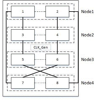
[0041] see image 3, which is a schematic diagram of the QPI connection in the 8S QPI subcard. For the case where the computing node has only 2 CPUs and the computing nodes are the same, the multi-channel server QPI subcard is installed on the mainboard computing node. There are 4 computing nodes, and the computing node Node1, Node2, Node3, Node4, the 2 CPU1 and CPU2 in Node1 are connected by the shortest distance QPI, the 2 CPU3 and CPU4 in Node2 are connected by the shortest distance QPI, the 2 CPU5 and CPU6 in Node3 are connected by the shortest distance QPI, and the 2 CPUs in Node4 are connected by the shortest distance The shortest distance QPI connection between CPU7 and CPU8 is indicated by the dotted line in the figure; CPU1 outside the computing node is connected to CPU3 and CPU7 through QPI, CPU2 is connected to CPU8 and CPU4 through QPI, CPU3 is connected to CPU1 and CPU5 through QPI, and CPU5 is connected to CPU8 through QPI It is connected to CPU3, CPU4 is connect...
PUM
 Abstract
Description
Claims
Application Information
 - R&D
- Intellectual Property
- Life Sciences
- Materials
- Tech Scout
- Unparalleled Data Quality
- Higher Quality Content
- 60% Fewer Hallucinations
Browse by: Latest US Patents, China's latest patents, Technical Efficacy Thesaurus, Application Domain, Technology Topic, Popular Technical Reports.
© 2025 PatSnap. All rights reserved.Legal|Privacy policy|Modern Slavery Act Transparency Statement|Sitemap|About US| Contact US: help@patsnap.com


