Detection method based on polarized light imaging technology

A detection method and technology of polarized light, applied in the field of image processing, can solve the problems of reduced system detection efficiency, low smoothness, poor readability of polarization parameter images, etc.

Inactive Publication Date: 2015-09-09
SHANGHAI YIYA IND CO LTD
View PDF2 Cites 9 Cited by
  • Summary
  • Abstract
  • Description
  • Claims
  • Application Information

AI Technical Summary

Problems solved by technology

Since the surface defect features of the object to be detected (such as scratches, uneven surface, low smoothness, etc.) are usually hidden and difficult to present in the intensity imaging system, this will bring greater pressure to the later image processing, which will not only increase the complexity of the algorithm degree, it will also reduce the detection efficiency of the system
Polarized light imaging detection is to obtain the target polarization information by obtaining the target reflected light in different polarization directions, and obtain the target polarization parameter information, such as polarization degree and polarization angle, by analyzing the target polarization information, and perform inversion calculation according to the target polarization parameter information. Target reconstructed graphics, the target reconstructed image includes polarization information of physical and chemical properties such as geometry, surface roughness, texture, conductivity, etc., but the surface and background of the target reconstructed image have certain differences in some polarization parameters from the original image. Polarization parameter images are less readable than intensity images and require post-interpretation

Method used


Image

  • Detection method based on polarized light imaging technology
  • Detection method based on polarized light imaging technology
  • Detection method based on polarized light imaging technology

Examples


Embodiment Construction

[0055] The present invention will be further described below in conjunction with the accompanying drawings and specific embodiments, but not as a limitation of the present invention.

[0056] The following will clearly and completely describe the technical solutions in the embodiments of the present invention with reference to the accompanying drawings in the embodiments of the present invention. Obviously, the described embodiments are only some, not all, embodiments of the present invention. Based on the embodiments of the present invention, all other embodiments obtained by persons of ordinary skill in the art without creative efforts fall within the protection scope of the present invention.

[0057] It should be noted that, in the case of no conflict, the embodiments of the present invention and the features in the embodiments can be combined with each other.

[0058] The present invention will be further described below in conjunction with the accompanying drawings and s...


PUM

PropertyMeasurementUnit
depthaaaaaaaaaa
lengthaaaaaaaaaa

Abstract

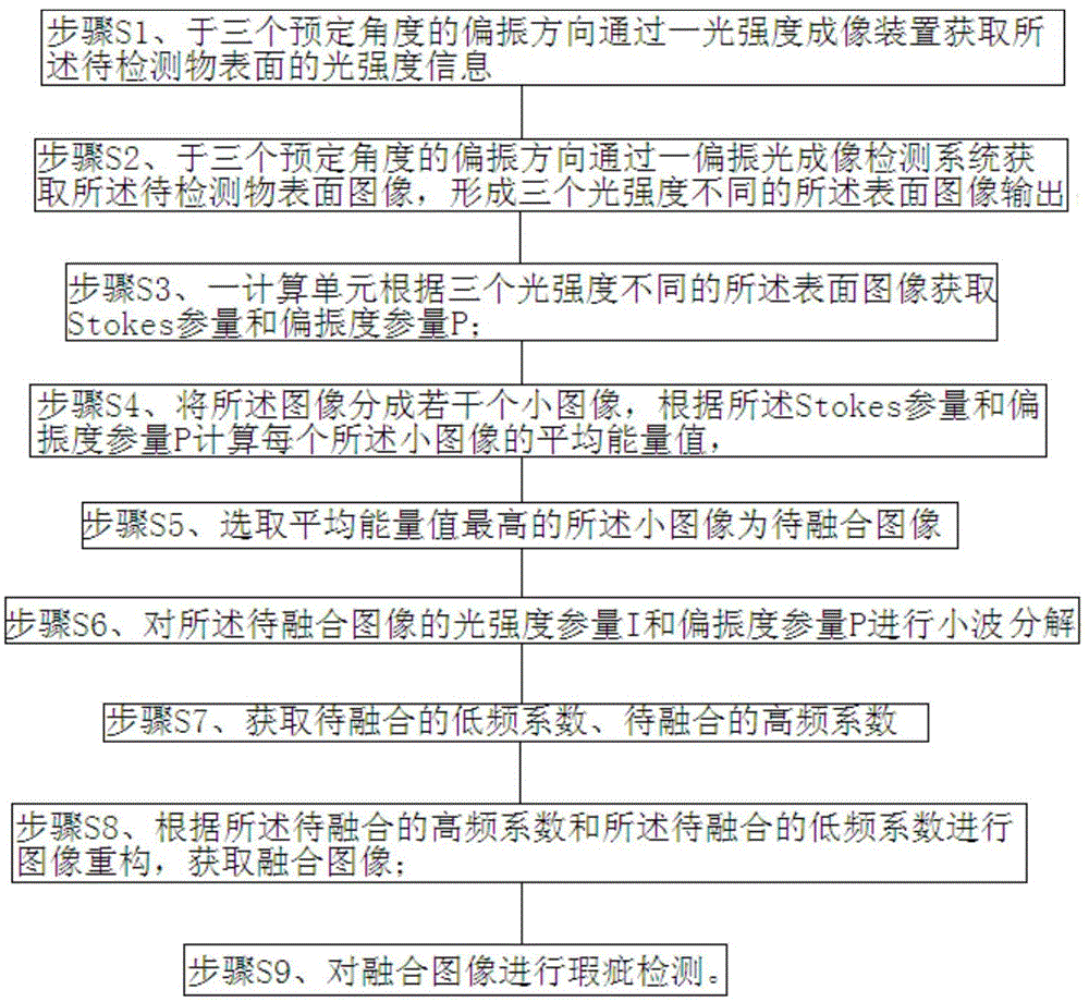
The invention relates to the technical field of image processing, and especially relates to a detection method and a detection device based on a polarized light imaging technology. According to the invention, polarized light imaging and intensity imaging principles are combined to fuse multi-source images, an enhanced fusion image is generated by utilizing complementation information in polarization image information and intensity image information, the details of the fusion image is more outstanding than that of any of polarization images and intensity images, and a new enhanced image deriving from the multi-source images is formed. The contrast of objective discrimination characteristics in the fusion image is far higher than the contrast of the objective discrimination characteristics in the intensity images, so that describing of relative scenes which is unable to obtained by a single image is realized, the limitation of the single image is overcome, the detection efficiency of objects to be detected is improved, and the accuracy of the detection efficiency is enhanced.

Description

technical field [0001] The invention relates to the technical field of image processing, in particular to a detection method based on polarized light imaging technology. Background technique [0002] Non-destructive testing technology, that is, non-destructive testing, uses the characteristics of sound, light, magnetism and electricity of the object to be detected to obtain information related to the quality of the object to be detected without destroying the original state and chemical properties of the object to be detected. The existing non-destructive testing methods used in industrial testing mainly include mechanical contact testing methods and photoelectric non-contact testing methods. Among them, the mechanical contact detection method is measured by the sliding of the stylus of the instrument on the surface to be tested. This method requires the stylus to make full contact with the surface of the object to be tested, so the detection speed is slow and it is easy to ...

Claims


Application Information

Patent Timeline
Patent Type & Authority Applications(China)
IPC IPC(8): G06T7/00G06T5/50G01N21/88
CPCG06T7/0008G01N21/8851G01N2021/8887G06T5/50G06T2207/10004G06T2207/20221G06T2207/30108
Inventor 刘晓王赟王勇
Owner SHANGHAI YIYA IND CO LTD
Why Eureka
Try Eureka