Method for designing thin cloth circular antenna array through changing auxiliary grid circle radius

A circular antenna and auxiliary grid technology, which is applied in the direction of antenna array, antenna, radiation element structure, etc., to achieve the effect of improving efficiency and accuracy, improving peak side lobe level, and reducing search space

Inactive Publication Date: 2015-09-09
UNIV OF ELECTRONICS SCI & TECH OF CHINA
View PDF1 Cites 19 Cited by
  • Summary
  • Abstract
  • Description
  • Claims
  • Application Information

AI Technical Summary

Problems solved by technology

In recent years, the method of using sparse array elements to reduce the side lobe l

Method used


Image

  • Method for designing thin cloth circular antenna array through changing auxiliary grid circle radius
  • Method for designing thin cloth circular antenna array through changing auxiliary grid circle radius
  • Method for designing thin cloth circular antenna array through changing auxiliary grid circle radius

Examples


Embodiment Construction

[0037] The optimized implementation of the present invention will be described in detail below.

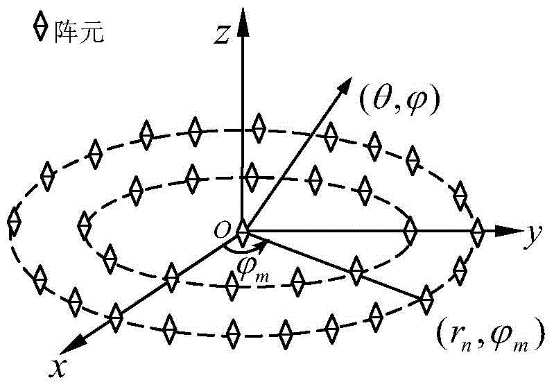
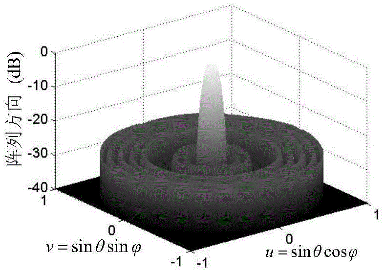
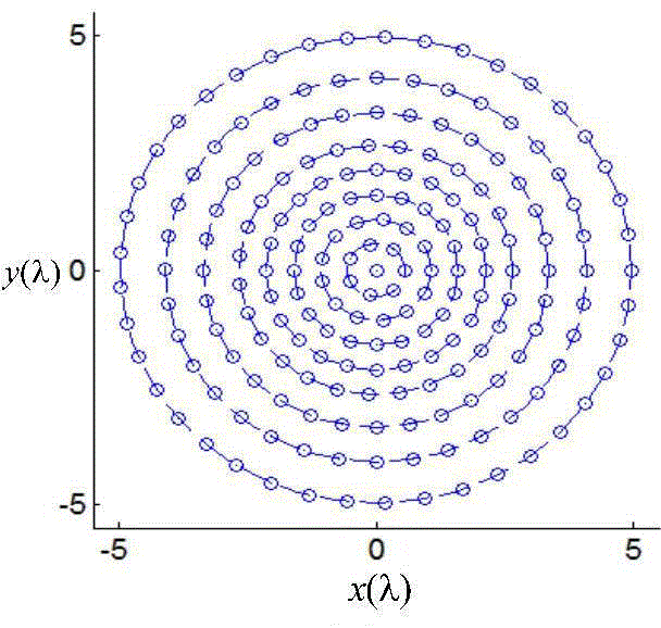
[0038] A simulation example of the present invention is given below. It can be seen from the accompanying drawings that the present invention proves its effectiveness by optimizing examples of the radius of the circular array in two cases. figure 1 Be the model of concentric ring array, the first instance is that the present invention optimizes array element number to be N=201, and population number is S=100, and genetic algebra is G=200, and minimum array element distance d c =0.5λ, the number of rings is H=7 and the aperture is L=9.96λ, a sparsely distributed concentric ring array. The simulation optimization results are shown in Table 1, figure 2 For its optimized array pattern, image 3 The array element distribution diagram after optimization. The second example is that the number of optimized array elements of the present invention is N=142, the population number is S=1...


PUM


Abstract

The invention discloses a method for designing a thin cloth circular antenna array through changing auxiliary grid circle radius. The method comprises the following steps that (1) distance between array elements on the same grid circular ring is constrained, range of the circular ring radius is confirmed according to the formula and S units are randomly generated so that an initial group is formed; and (2) the circular ring radius is optimized by utilizing a genetic algorithm, the optimal unit is iteratively outputted through intersection, mutation and selection, and peak side-lobe level of the optimal unit is calculated. Defects of graded optimization of the track circle radius and the number of the array elements on the track circle in existing circular array integrated methods are improved so that combined optimization of all the array elements is realized, lower peak side-lobe level is acquired, and optimization computation amount and model complexity are reduced.

Description

technical field [0001] The invention relates to the optimal design of circular array antennas, in particular to a method for designing a sparsely distributed circular antenna array by changing the radius of the auxiliary grid circle. Background technique [0002] The circular array can be stimulated by cyclically moving the array, and the azimuth of the beam can be manipulated simply and flexibly, and it also has an ideal directional characteristic in the elevation direction. At the same time, the symmetry of the circular structure keeps its beam shape and antenna gain basically balanced, and generally maintains a mutual coupling balance. Due to these advantages of the circular array, it is being used more and more widely, but the circular array pattern has a higher side lobe level than the main lobe. In recent years, the method of using sparse array elements to reduce the sidelobe level has become a research hotspot, but there are few studies on the circular radius. Cont...

Claims


Application Information

Patent Timeline
IPC IPC(8): H01Q1/36H01Q21/00
Inventor 陈客松朱永芸倪霄龙常全付
Owner UNIV OF ELECTRONICS SCI & TECH OF CHINA
Why Eureka
Try Eureka