Slot-coupled circularly-polarized micro-strip antenna

A microstrip antenna, circular polarization technology, applied in the direction of the antenna, electrical components, radiating element structure, etc., can solve the problems of radiation gain decline, large workload, and isolation resistance differential loss.

Active Publication Date: 2015-09-09
NO 54 INST OF CHINA ELECTRONICS SCI & TECH GRP
View PDF7 Cites 3 Cited by
  • Summary
  • Abstract
  • Description
  • Claims
  • Application Information

AI Technical Summary

Problems solved by technology

This kind of slot-coupled circularly polarized microstrip antenna needs to be loaded with isolation resistors to achieve a wider axial ratio bandwidth, which creates two problems: on the one hand, the isolation resistors need to be manually soldered, and when the array scale is large, a huge workload is required , and it is difficult to ensure the consistency of unit welding; on the other hand, the isolation resistance will produce a certain difference loss, resulting in different degrees of decline in radiation gain

Method used


Image

  • Slot-coupled circularly-polarized micro-strip antenna
  • Slot-coupled circularly-polarized micro-strip antenna
  • Slot-coupled circularly-polarized micro-strip antenna

Examples


Embodiment Construction

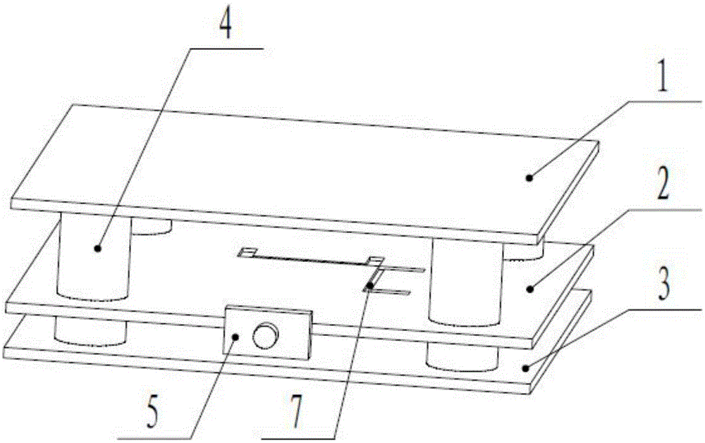
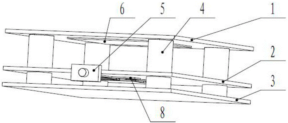
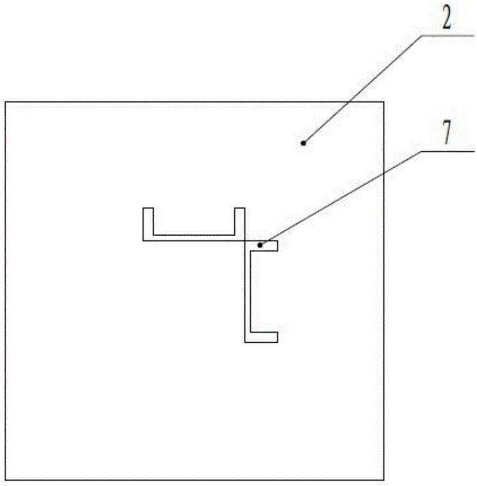
[0023] Such as figure 1 , figure 2 , image 3 , Figure 4 , Figure 5 As shown, a slot-coupled circularly polarized microstrip antenna includes a radiation patch layer dielectric plate 1, a feed network layer dielectric plate 2, and a reflective aluminum plate 3 arranged sequentially from top to bottom; the radiation patch layer dielectric plate 1 is A radiation patch 6 is applied on one side of the insulating dielectric board; the feeding network layer dielectric board 2 is coated with a copper thin film layer on one side of the insulating dielectric board, and two coupling grooves 7 are etched on the copper thin film layer. The other side of the insulating medium plate is coated with a circular polarization feed network 8; the circular polarization feed network 8 is sequentially composed of a receiving end 9, an equal power distribution section 10, a 90° phase shift section 11 and an open circuit branch 12; the coupling slot The shape of 7 is a concave shape, and the tw...


PUM


Abstract

The invention discloses a slot-coupled circularly-polarized micro-strip antenna. The slot-coupled circularly-polarized micro-strip antenna comprises a radiation paster layer medium plate, a feed network layer medium plate and a reflection aluminum plate which are arranged from up to down. The radiation paster layer medium plate is formed in such a manner that a radiation paster is applied to the side of an insulating medium plate. The feed network medium plate is formed in such a manner that a copper film layer is applied to the side of the insulating medium plate. Two coupled slots are formed in the copper film layer in an etching manner. A circularly-polarized feed network is applied to the other side of the insulating medium plate. The coupled slots are in a concave shape, the two concave-shaped coupled slots intersect on only one corner point, and the two coupled slots are perpendicular to each other and symmetrical. Both concave ports of the two concave-shaped coupled slots face the external part of the space commonly covered by the two concave-shaped coupled slots. The slot-coupled circularly-polarized micro-strip antenna is different from a conventional straight slot design, bent parts of the concave slots are capable of realizing tuning of an antenna standing wave curve, and the two concave slots are arranged in a perpendicular and symmetrical manner, so that two electromagnetic waves which are orthogonal in polarity and identical in amplitude are guaranteed to be excited.

Description

technical field [0001] The invention relates to a microstrip antenna in the fields of communication and measurement and control, in particular to a slot coupling circularly polarized microstrip antenna. Background technique [0002] An existing slot-coupled circularly polarized microstrip antenna includes a radiation patch layer dielectric board, a feed network layer dielectric board, and a reflective aluminum board arranged in sequence from top to bottom; the radiation patch layer dielectric board is placed on the insulating dielectric board One side of the board is coated with a copper thin film layer for radiating or receiving circularly polarized electromagnetic signals, and the copper thin film layer is called a radiation patch; the feeding network layer dielectric board is coated with a copper thin film layer on one side of the insulating dielectric board , two coupling grooves are etched on the copper film layer, and a circularly polarized feed network is laid on the ...

Claims


Application Information

Patent Timeline
Patent Type & Authority Applications(China)
IPC IPC(8): H01Q1/38H01Q13/08H01Q1/36
Inventor 宋长宏路志勇王涛赵航王海赵楠王焕菊
Owner NO 54 INST OF CHINA ELECTRONICS SCI & TECH GRP
Why Eureka
Try Eureka