Method of fabricating a curved composite structure using composite prepreg tape

A composite structure, prepreg tape technology, applied in applications, household components, household appliances, etc., can solve the problems of increased material cost, time consumption, reduced productivity, etc., to reduce time, prevent plies from wrinkling and/or warping Curvature, strength and appearance improvements

Active Publication Date: 2015-09-09
THE BOEING CO
View PDF6 Cites 1 Cited by
  • Summary
  • Abstract
  • Description
  • Claims
  • Application Information

AI Technical Summary

Problems solved by technology

However, the use of slit tape can increase material costs and reduce productivity because laying the slit tape can be more time-consuming

Method used


Image

  • Method of fabricating a curved composite structure using composite prepreg tape
  • Method of fabricating a curved composite structure using composite prepreg tape
  • Method of fabricating a curved composite structure using composite prepreg tape

Examples


Embodiment Construction

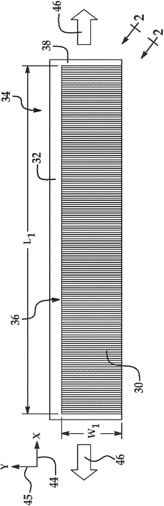
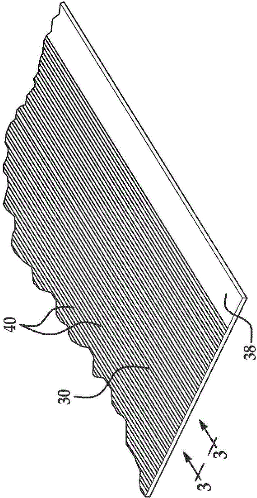
[0049] first reference figure 1 , 2 as well as image 3 , ply 30 of composite resin material is held in face-to-face contact with carrier film 32 to form ply carrier assembly 34 . Carrier film 32 may be used to transport ply 30 and / or apply ply 30 to a tool (not shown) during a layup process to produce a composite part layup (not shown). exist Figure 1-3 In the example illustrated in , ply 30 may be a prepreg containing unidirectional reinforcing fibers 40 with a 90 degree orientation, however, other plies (not shown) within the part layup may have ply configurations based on predetermined other fiber orientations.

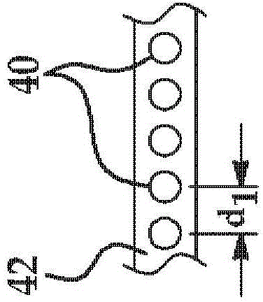
[0050] The fibers 40 are pre-impregnated with a suitable polymeric resin 42 which acts as a matrix to hold the fibers 40 in the desired orientation after curing. Prior to deformation during the lamination process, the composite ply 30 has a length L 1 and width W 1 , as will be described in more detail below. Ply 30 is bonded to carrier film 32 by the tac...


PUM


Abstract

A method is provided of fabricating a composite stiffener having a curved web and at least one curved flange. A substantially straight length of unidirectional prepreg tape (30) is placed on a carrier (32). The at least one curved flange is formed by using the carrier to steer a first portion of the tape onto a first curved tool surface. The curved web is formed by using the carrier to form a second portion of the tape onto a second curved tool surface.

Description

technical field [0001] The present disclosure relates generally to processes for fabricating curved composite structures, and more particularly to methods of fabricating composite structures, such as fabricating stiffeners with composite curves using composite prepreg tapes. Background technique [0002] During layup of prepreg plies on a tool, it is sometimes necessary to closely conform the plies to the curves, contours and / or features of the tool in order to ensure that the fibers follow the load path and that the layup is of accurate dimensions and substantially free of voids, wrinkling and / or warping. Known techniques for conforming the plies to curved tool surfaces include projecting, cutting and / or separating the plies during the lamination process, and / or extensive manual sweeping to conform the plies to the contoured tool surface. These techniques can be time consuming, and / or may not result in the desired mechanical strength of the bent part. Another solution to ...

Claims


Application Information

Patent Timeline
Patent Type & Authority Applications(China)
IPC IPC(8): B29C70/54B29C70/20B29C70/30B64C1/06B29L31/00
CPCB29C70/20B29C70/30B64C1/064Y02T50/433B29C70/541B29L2031/003B29D99/0003Y02T50/40B29C70/54
Inventor D·R·史密斯A·E·莫丁E·迪帕斯D·C·达罗M·克莱微亚达
Owner THE BOEING CO
Why Eureka
Try Eureka