
Flange protective cover

A protective cover and flange technology, applied in the field of flange protective covers, can solve the problems of poor safety protection such as anti-corrosion and waterproof, poor air tightness of the protective cover, and difficult disassembly and assembly, etc., to achieve good sealing, simple structure, and easy disassembly. The effect of convenient installation

Inactive Publication Date: 2015-09-16
国投钦州发电有限公司
View PDF7 Cites 3 Cited by
  • Summary
  • Abstract
  • Description
  • Claims
  • Application Information

AI Technical Summary

Problems solved by technology

[0003] And the existing flange protective cover is mainly divided into two kinds, one is made of stainless steel, this kind of protective cover has good anticorrosion and anti-rust performance, but it is expensive and not easy to disassemble; the other is made of soft stainless steel. Made of durable materials, such as the Chinese utility model patent whose authorized announcement number is CN204021515U discloses a pipe flange protective cover, including a cover body (1), and the cover body (1) includes a side wall (4) and a bottom surface (2 ), the inside of the bottom surface (2) is used to cover the pipe opening, the side wall (4) includes a lower end (48) and an upper end (49), the lower end (48) is connected with the bottom surface (2), and the lower end ( 48) and the bottom surface (2) are both made of polypropylene non-woven fabric or composite leather, and the upper end (49) is made of soft material and surrounds to form an open end (3); the side wall (4) is provided with There is an adjustment piece (42) for adjusting the diameter of the open end (3)
The flange protective cover of this structure is cheap and easy to use, but its anti-corrosion, waterproof and other safety protection effects are poor, and the airtightness of the protective cover is poor

Method used


Image

  • Flange protective cover
  • Flange protective cover
  • Flange protective cover

Examples


Embodiment Construction

[0023] The present invention will be further explained below in conjunction with the accompanying drawings and specific embodiments, but not intended to limit the present invention.

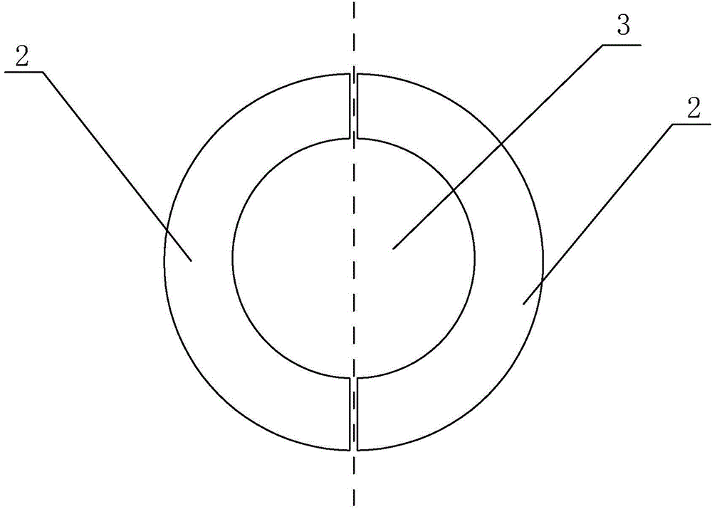
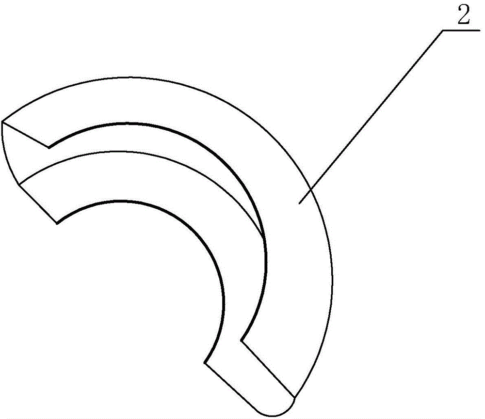
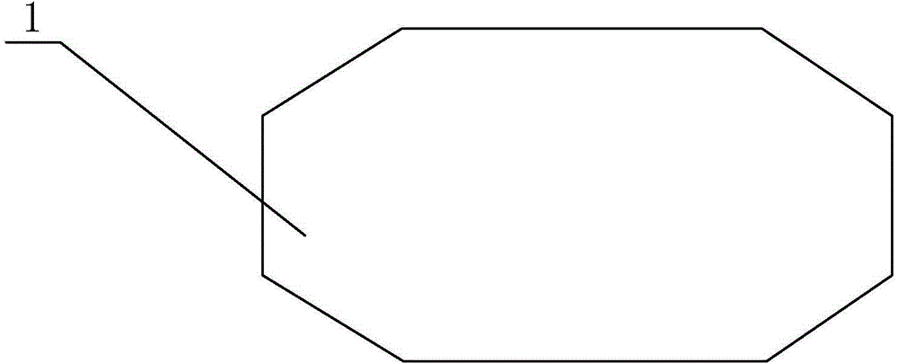
[0024] Such as figure 1 , figure 2 As shown, a flange protection cover includes a closed cover body 1 with a hollow inside, and two circular holes 3 for the pipeline 4 to pass through are opened on the cover body 1, and along the direction where the circular holes 3 are located The central axis divides the cover body 1 into two matching half-disks 2, and the two matching half-discs 2 are movably connected so that the two half-discs 2 can be separated from each other. The cover body 1 is a hard shell , the diameter of the circular hole 3 should be slightly larger than the diameter of the installed pipeline 4, so that the pipeline 4 can pass through the circular hole 3; A soft sealing strip is provided at the contact point, one end of the soft sealing strip is fixed on the cover body 1 , and the...


PUM


Abstract

The invention discloses a flange protective cover which comprises an internally hollow sealing-type cover body, wherein two round holes used for pipeline passing are disposed in the cover body, the cover body is divided into two coordinated half disks along the center axis of the round holes, the two coordinated half disks are movably connected to realize mutual separation of the two half disks, and the cover body is a hard shell body. By the two half disks used through coordination, the flange cover body disposes a flange, a partial pipeline connected on the flange and a flange bolt sleeve inside the cover body, and realizes sealing by a soft sealing bars; and the cover body is the hard shell body. In comparison with existing flange protective covers, the flange protective cover provided by the invention can separate flange components from external air very well, and is characterized by good sealing effect, a simple structure and convenient disassembly and assembly.

Description

technical field [0001] The invention relates to a flange protection tool, in particular to a flange protection cover, which belongs to the technical field of industrial production equipment. Background technique [0002] In industrial production and daily life, there will be a large number of pipeline connections. When the fluid in the pipeline is greater than 4Mpa or the diameter of the pipeline is large, flange connection is required. The adjacent two flanges are fixed with bolts, and the flange is installed Gaskets are often used during the connection to prevent fluid penetration. The use of flanges makes it possible to transmit high-temperature, high-pressure fluids over long distances. However, when the flange is in use, it is usually exposed to the air, exposed to wind, sun and rain, so it will inevitably get rusty, and the bolts used to connect the flange will also get rusty. Corrosion damage of flanges and bolts will not only damage the pipeline equipment, but also...

Claims


Application Information

Patent Timeline
IPC IPC(8): F16L23/00F16L58/18
CPCF16L23/006F16L58/18F16L2201/20F16L2201/30
Inventor 武伟朱逢民李洪庆孙学艳林川张安泰
Owner 国投钦州发电有限公司
Features
  • Generate Ideas
  • Intellectual Property
  • Life Sciences
  • Materials
  • Tech Scout
  • Unparalleled Data Quality
  • Higher Quality Content
  • 60% Fewer Hallucinations
Learn More