Lamp base, LED lamp fixture and LED lamp

A technology of LED lamps and LED lamps, applied in the field of lighting, can solve the problems of shortened service life, aging and failure of electronic components, complicated optical path design of LED lamp 02, etc.

Inactive Publication Date: 2015-09-16
唐水 +1
View PDF6 Cites 7 Cited by
  • Summary
  • Abstract
  • Description
  • Claims
  • Application Information

AI Technical Summary

Problems solved by technology

[0004] But there are some defects in the existing LED lamps: the control communication board 022 and the power supply board 023 are arranged inside the radiator 021, and the temperature inside the radiator is relatively high, and the electronic components on the control communication board 022 and the power supply board 023 are such as electrolytic capacitors 026 is very sensitive to the ambient temperature, therefore, when the LED chip 025 generates heat, the heat will be transferred to the radiator 021 along the direction indicated by the arrow A, so that the temperature of the radiator 021 will gradually increase, and the heat in the radiator 021 will be Inward or outward...

Method used


Image

  • Lamp base, LED lamp fixture and LED lamp
  • Lamp base, LED lamp fixture and LED lamp
  • Lamp base, LED lamp fixture and LED lamp

Examples


Embodiment 1

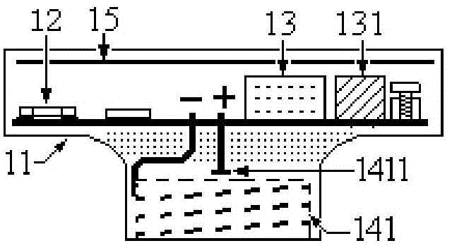
[0105] see Figure 2-1 and Figure 2-2 , Figure 2-1 It is a cross-sectional view of a lamp holder disclosed in Embodiment 1 of the present invention, Figure 2-2 It is a cross-sectional view of another lamp holder disclosed in Embodiment 1 of the present invention. Figure 2-1 and Figure 2-2 The shown lamp socket is used for installing an LED lamp, and the lamp socket includes a housing 11 , a communication control circuit 12 , a power supply circuit 13 and a first interface.

[0106] in:

[0107] The housing 11 has an insulating cavity. In practice, the casing 11 may be a closed structure. In addition, the housing 11 can also be set such that the position where the bottom of the housing 11 combines with the first interface is in a closed state. At this time, no gap can be left at the position where the power cord (or screw) passes through the housing 11, and a hole can be punched on the housing 11. The aperture of the hole matches the diameter of the power cord (or s...

Embodiment 2

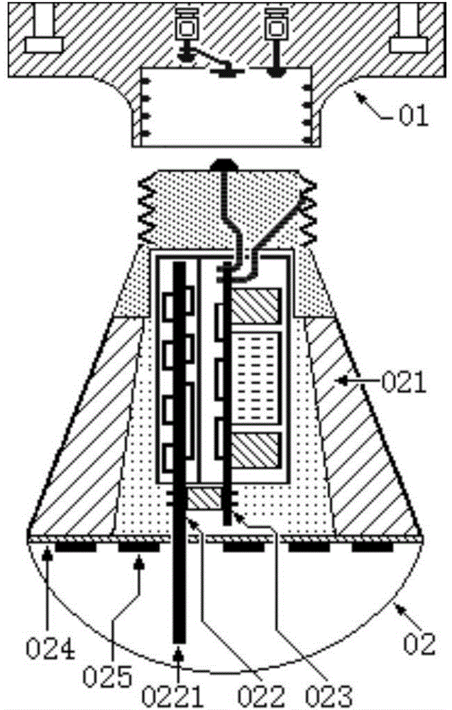
[0151] see Figure 3-1 and Figure 3-2 , Figure 3-1 It is a split sectional view of an LED lamp disclosed in Embodiment 2 of the present invention, Figure 3-2 It is a split sectional view of another LED lamp disclosed in Embodiment 2 of the present invention. The LED lamp includes a lamp holder and an LED lamp, wherein the lamp holder includes a housing 11 , a communication control circuit 12 , a power circuit 13 and a first interface, and the LED lamp includes a heat sink 21 , a third interface, an LED substrate 22 and an LED chip 23 .

[0152] The housing 11 has an insulating cavity. In practice, the casing 11 may be a closed structure. In addition, the housing 11 can also be set such that the position where the bottom of the housing 11 combines with the first interface is in a closed state. At this time, no gap can be left at the position where the power cord (or screw) passes through the housing 11, and a hole can be punched on the housing 11. The aperture of the ho...

Embodiment 3

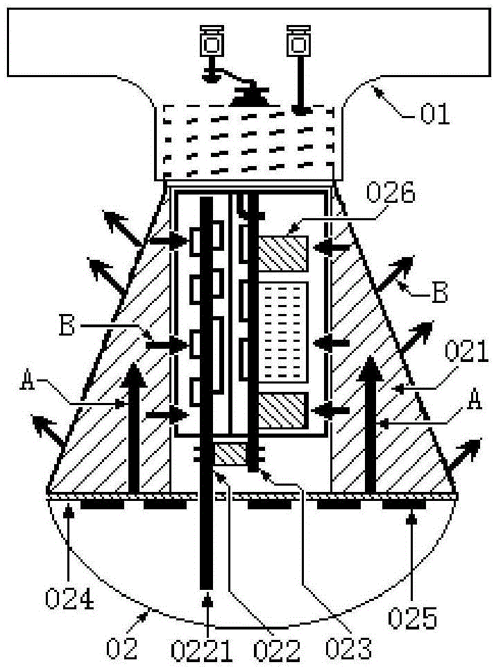
[0207] see Pic 4-1 , Figure 4-2 and Figure 4-4 , Pic 4-1 It is a cross-sectional view of an LED lamp disclosed in Embodiment 3 of the present invention, Figure 4-2 It is a cross-sectional view of another LED lamp disclosed in Embodiment 3 of the present invention, Figure 4-4It is a cross-sectional view of another LED lamp disclosed in Embodiment 3 of the present invention. The LED lamp comprises a lamp holder and an LED lamp fixed on the lamp holder.

[0208] The lamp holder includes a housing 31 , a communication control circuit 32 and a power supply circuit 33 , and the LED lamp includes a radiator 34 , an LED substrate 35 and an LED chip 36 . in:

[0209] The radiator 34 is connected to the housing 31 . In practice, the radiator 34 may be located at the bottom of the casing 31 . Of course, the radiator 34 can also be located in other positions of the housing 31, such as Figure 4-6 , Figure 4-8 , Figure 4-9 , Figure 4-10 , Figure 4-11 and Figure 4-1...


PUM


Abstract

In an LED lamp fixture disclosed in the invention, a communication control circuit and a power source circuit are disposed inside a chamber of a shell body, and a radiator equipped with an LED baseplate and an LED chip is located outside the shell body, so that the space in which the communication control circuit and the power source circuit are located is separated from the space in which the radiator is located, environmental temperature of the communication control circuit and the power source circuit is then reduced, aging of the communication control circuit and the power source circuit caused by a high temperature is prolonged, an aging rate of an electrolytic capacitor in the power source circuit is especially reduced, and thus service life of the LED lamp fixture is increased. In addition, a communication module in the communication control circuit has good working performances and also reduces design difficulty of an optical path. The invention also discloses a lamp base and an LED lamp.

Description

technical field [0001] The invention belongs to the technical field of illumination, and in particular relates to a lamp holder, an LED (light emitting diode) lamp and an LED lamp. Background technique [0002] With the continuous development of Internet of Things technology and smart home technology, new smart LED lights have also entered the field of lighting to realize on / off control of LED lights, brightness adjustment, color temperature or color adjustment, abnormal work detection, working temperature detection, and power consumption. Electrical detection, etc., and remote or short-range control can be performed wirelessly, which greatly realizes the intelligent management of LED lights. There are many wireless networking solutions: infrared solutions, 315MHz radio frequency solutions, 433MHz radio frequency solutions, Z-Wave solutions (European frequency band is 868.42MHz, US frequency band is 908.42MHz), 2.4GHz and 5GHz Wi-Fi solutions, 2.4GHz ZigBee solutions, 2.4GH...

Claims


Application Information

Patent Timeline
IPC IPC(8): F21S2/00F21V23/06F21V23/04F21V19/00F21V29/503F21Y101/02
CPCF21S2/00F21V19/001F21V23/045F21V23/06
Inventor 唐水
Owner 唐水
Why Eureka
Try Eureka