Phased array quantitative damage monitoring method, phased array quantitative damage monitoring device and phased array quantitative damage monitoring system

A damage monitoring and phased array technology, which is applied in the analysis of solids using sound waves/ultrasonic waves/infrasonic waves, can solve problems such as difficulty in signal analysis and interpretation, consistent initial phase of wave packets, and distortion of beamforming signal waveforms.

Active Publication Date: 2015-09-16
BEIJING AERONAUTIC SCI & TECH RES INST OF COMAC +1
View PDF5 Cites 6 Cited by
  • Summary
  • Abstract
  • Description
  • Claims
  • Application Information

AI Technical Summary

Problems solved by technology

[0007] The disadvantage of the above-mentioned first method is that: using the time-distance domain mapping dispersion compensation method, it is easy to cause the waveform of the beamforming signal to be distorted, which makes it difficult for subsequent signal analysis and interpretation
[0008] Although the above-mentioned second method can restore the envelope shape of the wave packet in each scattered signal, it cannot keep the initial phase inside the wave packet consistent. When the monitoring range is expanded, this phase inconsistency will not be ignored, thereby reducing the subsequent time. Accuracy of Domain Beamforming
Moreover, current phased array damage monitoring methods generally only provide imaging results, and less quantitative information such as damage location and severity

Method used


Image

  • Phased array quantitative damage monitoring method, phased array quantitative damage monitoring device and phased array quantitative damage monitoring system
  • Phased array quantitative damage monitoring method, phased array quantitative damage monitoring device and phased array quantitative damage monitoring system
  • Phased array quantitative damage monitoring method, phased array quantitative damage monitoring device and phased array quantitative damage monitoring system

Examples


Embodiment 1

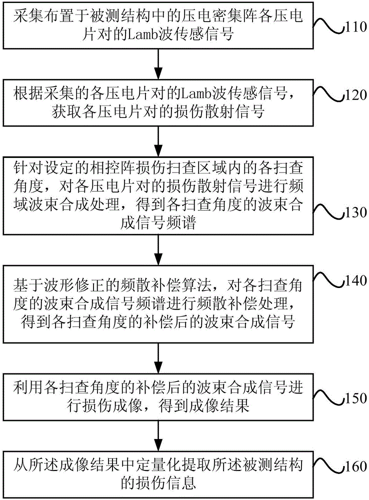
[0047] see figure 1 , is a schematic flowchart of a phased array quantitative damage monitoring method provided in Embodiment 1 of the present invention. The method of the embodiment of the present invention can be executed by a phased array quantitative damage monitoring device configured with hardware and / or software, and the implementation device can be configured to include a piezoelectric dense array corresponding to the structure under test and signal generation and acquisition. In the phased array quantitative damage monitoring system of the device.

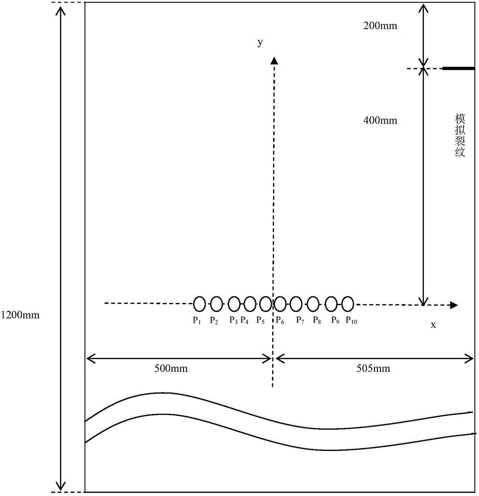
[0048]Taking the phased array quantitative monitoring of cracks in the aluminum plate structure as an example, the method of the embodiment of the present invention will be described. However, the structure to be tested in this embodiment is not limited to the aluminum plate structure in the example.

[0049] Firstly, the tested structure is introduced. It is a 2024 aluminum plate structure commonly used in aircraft, wit...

Embodiment 2

[0104] see Figure 15 , is a schematic structural diagram of a phased array quantitative damage monitoring device provided in Embodiment 2 of the present invention. The device includes: a signal acquisition module 210 , a beam synthesis processing module 220 and a damage identification module 230 .

[0105] Wherein, the signal collection module 210 is used to collect the Lamb wave sensing signals of each pair of piezoelectric sheets of the piezoelectric ensemble arranged in the structure under test.

[0106] Specifically, the signal acquisition module 210 can realize the acquisition of Lamb wave sensing signals through the piezoelectric dense array corresponding to the signal generator and the structure under test. That is, through the signal generation and acquisition device, an excitation signal is applied to the piezoelectric sheet as the exciter in the pair of piezoelectric sheets contained in the piezoelectric ensemble corresponding to the structure under test, and each ...

Embodiment 3

[0141] see Figure 16 , is a schematic structural diagram of a phased array quantitative damage monitoring system provided in Embodiment 3 of the present invention. The system includes: a piezoelectric dense array 310 and a signal generator and collector 320 corresponding to the structure to be tested, and also includes: a phased array quantitative damage monitoring device 330 provided by any embodiment of the present invention.

[0142] Specifically, the phased array quantitative damage monitoring device 330 can collect the Lamb wave of each piezoelectric sheet pair of the piezoelectric ensemble arranged in the structure under test through the piezoelectric ensemble corresponding to the collector and the structure under test. sensing signal.

[0143] In the above solution, the signal generating and collecting unit 320 may specifically include: a signal generating unit, a power amplifying unit, a multiplexing unit, a signal conditioning unit, and a signal collecting unit.

...


PUM

PropertyMeasurementUnit
diameteraaaaaaaaaa
thicknessaaaaaaaaaa

Abstract

The invention provides a phased array quantitative damage monitoring method, a phased array quantitative damage monitoring device and a phased array quantitative damage monitoring system. The method comprises the steps of acquiring Lamb wave sensing signals of piezoelectric wafer pairs of piezoelectric close-packed array in a tested structure; acquiring the damage scattering signals of the piezoelectric wafer pairs; carrying out frequency domain beam forming processing on the damage scattering signals to obtain a beam forming signal frequency spectrum of scanning angles; carrying out the frequency dispersion compensating processing on the beam forming signal frequency spectrum by a frequency dispersion compensating algorithm based on wave form correcting to obtain the compensated beam forming signals of the scanning angles; carrying out damage imaging by utilizing beam forming signals to obtain an imaging result; and extracting the damage information of the tested structure in the imaging result. According to the method, the influence on the beam forming process caused by the frequency dispersion effect can be eliminated, the distortion of the wave forms of the beam forming signals subjected to the frequency dispersion compensating can be avoided, the signal interpretation and the subsequent phased array high-resolution damage imaging are convenient, and further, two damage information, namely the damage position and the degree of severity can be given in a quantification manner.

Description

technical field [0001] Embodiments of the present invention relate to the technical field of structural health monitoring, in particular to a phased array quantitative damage monitoring method, device and system. Background technique [0002] With the increasing requirements for structural safety and reliability, structural health monitoring has gradually received attention. The phased array damage monitoring method uses the beam-synthesized Lamb wave monitoring signals at various scanning angles to quickly perform large-area virtual omnidirectional scanning imaging on the structure and provide structural damage information, which has attracted extensive attention from damage monitoring researchers. [0003] However, in the actual application of phased array damage monitoring, the dispersion characteristics of Lamb waves can easily expand and deform the signal waveform, which seriously affects the phased array beamforming process and reduces the accuracy and resolution of ph...

Claims


Application Information

Patent Timeline
Patent Type & Authority Applications(China)
IPC IPC(8): G01N29/04
Inventor 蔡建卿新林袁慎芳鲁明宇高丽敏
Owner BEIJING AERONAUTIC SCI & TECH RES INST OF COMAC
Why Eureka
Try Eureka