Relay control circuit

A relay control and circuit technology, applied in the direction of relays, circuits, electrical components, etc., can solve the problems of reduced service life of relays, high heat generation, high power consumption of relays, etc., and achieve the effect of reducing power consumption and stabilizing control signals

Inactive Publication Date: 2015-09-16
CHENGDU GUANGMAI TECH
View PDF6 Cites 5 Cited by
  • Summary
  • Abstract
  • Description
  • Claims
  • Application Information

AI Technical Summary

Problems solved by technology

The disadvantage of this solution is that the relay has been working under a high load state, resulting in a large power consumption and a large heat generation of the relay itself, which reduces the service life of the relay

Method used


Image

  • Relay control circuit

Examples


Embodiment Construction

[0009] The following will clearly and completely describe the technical solutions in the embodiments of the present invention with reference to the accompanying drawings in the embodiments of the present invention. Obviously, the described embodiments are only some, not all, embodiments of the present invention. Based on the embodiments of the present invention, all other embodiments obtained by persons of ordinary skill in the art without making creative efforts belong to the protection scope of the present invention.

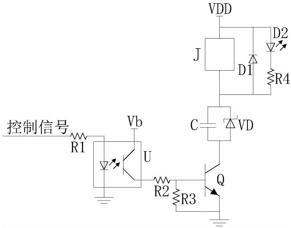
[0010] see figure 1 , is a schematic diagram of the circuit principle of the relay control circuit of the embodiment of the present invention. The relay control circuit of this embodiment includes a photocoupler U, a first resistor R1, a second resistor R2, a third resistor R3, a transistor Q, a capacitor C, a Zener diode VD, a relay coil J, a diode D1, a light emitting diode D2 and The fourth resistor R4.

[0011] Wherein, the photocoupler U has two input e...


PUM


Abstract

The present invention provides a relay control circuit. The relay control circuit comprises a photoelectric coupler, a first resistor, a second resistor, a third resistor, a triode, a capacitor, a voltage stabilizing diode, a relay coil, a diode, a light emitting diode and a fourth resistor; one input end of the photoelectric coupler is connected with a control signal by the first resistor and the other input end of the photoelectric coupler is grounded; one output end of the photoelectric coupler is connected with a bias voltage and the other output end of the photoelectric coupler is connected with a base of the triode by the second resistor; an emitter of the triode is grounded; the third resistor is connected between the base and the emitter of the triode; a collector of the triode is connected with an anode of the voltage stabilizing diode and one end of the capacitor; a cathode of the voltage stabilizing diode and the other end of the capacitor are connected with one end of the relay coil and an anode of the diode; the other end of the relay coil and a cathode of the diode are connected with a power supply voltage; a cathode of the light emitting diode is connected with the anode of the diode by the fourth resistor; and an anode of the light emitting diode is connected with the cathode of the diode. According to the present invention, power consumption of a relay can be reduced.

Description

technical field [0001] The invention relates to the technical field of relay control, in particular to a relay control circuit. Background technique [0002] The relay is an electronic control device, which is an "automatic switch" that uses a smaller current to control a larger current. Therefore, it plays the role of automatic adjustment, safety protection, and conversion circuit in the circuit. [0003] Most of the current relay control methods use the nominal pull-in voltage of the relay to directly supply the relay. The disadvantage of this solution is that the relay has been working under a high load state, resulting in a large power consumption and a large heat generation of the relay itself, which reduces the service life of the relay. Contents of the invention [0004] The technical problem mainly solved by the invention is to provide a relay control circuit, which can reduce the power consumption of the relay. [0005] In order to solve the above technical pro...

Claims


Application Information

Patent Timeline
Patent Type & Authority Applications(China)
IPC IPC(8): H01H47/02
CPCH01H47/02
Inventor 张科韩秋月
Owner CHENGDU GUANGMAI TECH
Why Eureka
Try Eureka