
A High Gain Horn Antenna Based on Metamaterial Loading

A horn antenna and metamaterial technology, applied in the directions of antennas, electrical components, radiating components, etc., can solve the problems of difficulty in analyzing the coupling characteristics of each layer structure, large processing errors of the three-layer transmission surface, and long design cycle, and achieve the goal of preparing The effect of short period, improved radiation gain and low cost

Active Publication Date: 2018-05-25
UNIV OF ELECTRONICS SCI & TECH OF CHINA
View PDF16 Cites 2 Cited by
  • Summary
  • Abstract
  • Description
  • Claims
  • Application Information

AI Technical Summary

Problems solved by technology

It’s just that the processing error of the three-layer transmissive surface is large, the cost is high, and the analysis of the coupling characteristics between the structures of each layer is difficult, resulting in a long design cycle

Method used


Image

  • A High Gain Horn Antenna Based on Metamaterial Loading
  • A High Gain Horn Antenna Based on Metamaterial Loading
  • A High Gain Horn Antenna Based on Metamaterial Loading

Examples


Embodiment Construction

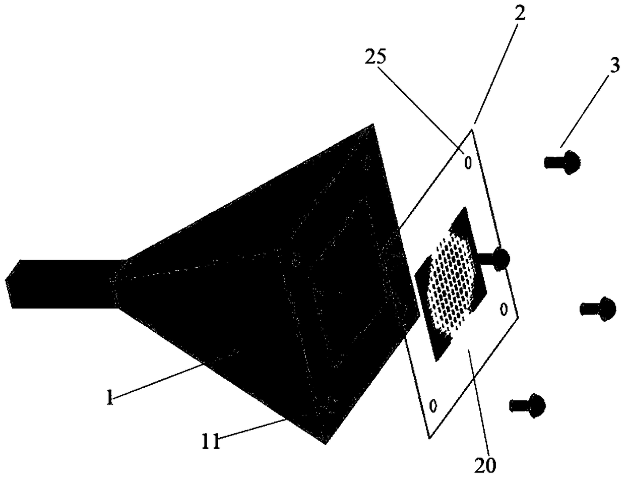
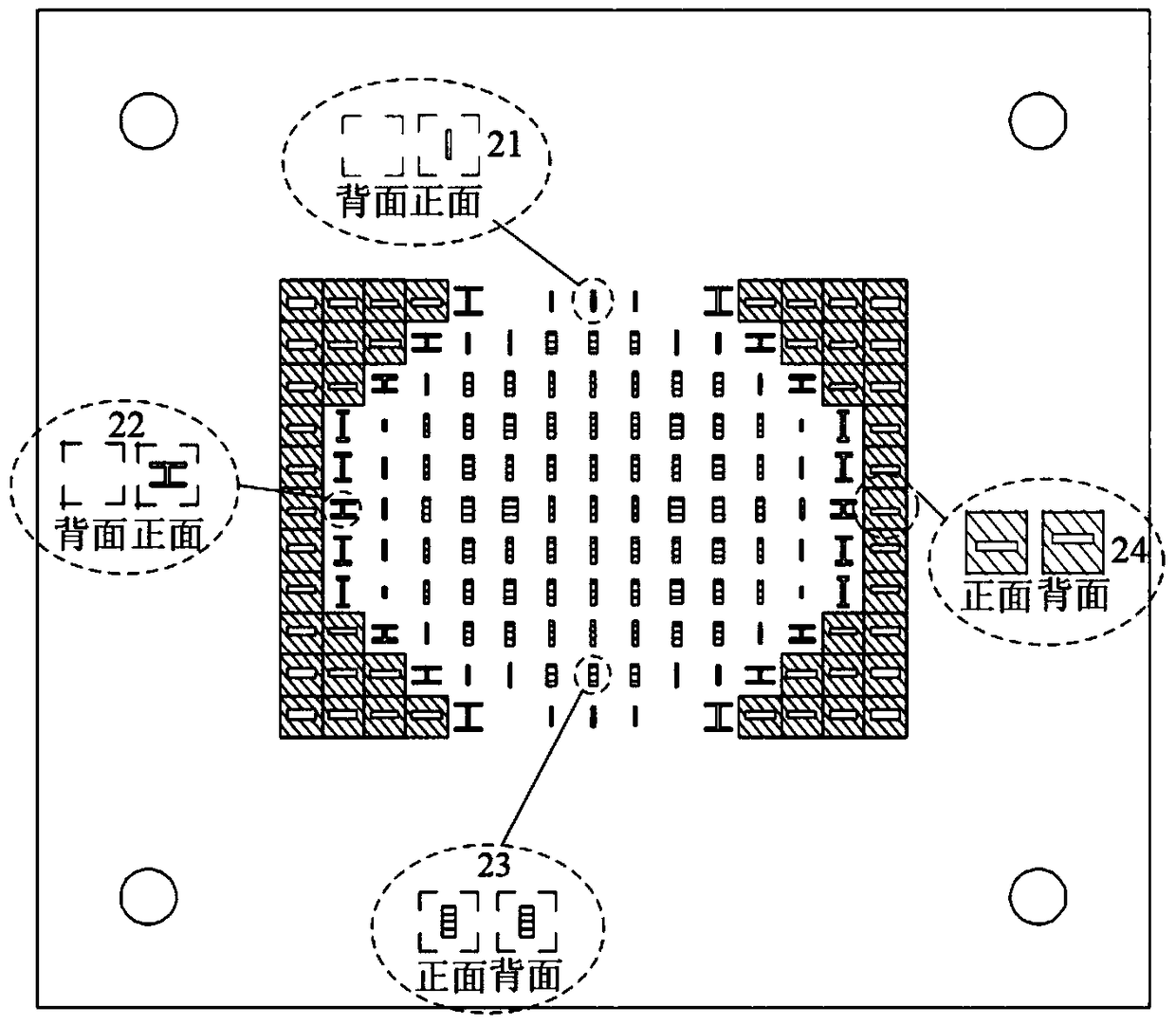
[0016] Such as figure 1 As shown in the schematic diagram of the overall structure of , a high-gain horn antenna based on metamaterial loading includes a standard horn antenna 1, a metamaterial plate 2, and four screws 3 for positioning and fixing the metamaterial plate. The metamaterial flat plate 2 consists of 22 first metamaterial structural units 21, 22 second metamaterial structural units 22, and 73 third metamaterial structural units printed on both sides of a low-loss Rogers5880 dielectric substrate 20 with a thickness of 0.127mm. The structural unit 23 and 46 fourth metamaterial structural units 24 are closely arranged in parallel, and four through holes 25 for positioning and fixing are drilled at the four corners of the metamaterial flat plate; the standard horn antenna 1 is selected to work at 75-110 GHz The W-band standard pyramid horn antenna is drilled with four screw holes 11 for positioning and fixing at the four corners of its output end face; The four throug...


PUM


Abstract

The invention discloses a high-gain horn antenna based on metamaterial loading, which includes a standard horn antenna, a metamaterial plate, and four screws for positioning and fixing the metamaterial plate. Four kinds of metamaterial structural units are arranged in parallel and close to each other. When loaded on the output port surface of a standard horn antenna, the electromagnetic wave amplitude and phase distribution of the horn antenna can be adjusted to achieve high-gain radiation. The invention can be used in microwave and millimeter wave communication and radar antenna feeder systems, and has the advantages of being suitable for miniaturization, light weight, integration, and low cost of antenna feeder systems, and its processing cycle is short, and various radiation properties can be replaced by It can be easily realized by a metamaterial slab arranged with different structural units.

Description

technical field [0001] The invention belongs to the technical field of microwave and millimeter wave antennas, and relates to a high-gain horn antenna. Background technique [0002] The horn antenna is a commonly used antenna form in modern communication and radar systems. Because of its high power capacity and low loss, it is especially suitable for high-power and extremely high-frequency systems. However, with the rapid development of modern communication and radar systems, the electrical performance requirements of microwave and millimeter wave antennas are getting higher and higher, and at the same time, they are also developing in the direction of miniaturization, light weight, integration, and low cost. Therefore, the horn antenna Improved design remains a hot topic in science as well as industry. [0003] In order to improve the radiation gain of the horn antenna and realize the long-distance work of the system, Yang Rui and others disclosed a high-gain ultra-wideban...

Claims


Application Information

Patent Timeline
Patent Type & Authority Patents(China)
IPC IPC(8): H01Q15/08H01Q1/38
Inventor 林先其于家伟梅鹏陈哲聂丽瑛江源张瑾侯岳峰
Owner UNIV OF ELECTRONICS SCI & TECH OF CHINA
Learn More