
CMOS oscillator

An oscillator and inverter technology, applied in pulse generation, electrical components, generating electrical pulses, etc., can solve problems such as increasing circuit area and cost, increasing circuit structure complexity, and offset voltage oscillator output frequency deviation. Reduced area and cost, fast response time at power-on and improved circuit structure

Inactive Publication Date: 2015-09-16
UNIV OF ELECTRONICS SCI & TECH OF CHINA
View PDF4 Cites 5 Cited by
  • Summary
  • Abstract
  • Description
  • Claims
  • Application Information

AI Technical Summary

Problems solved by technology

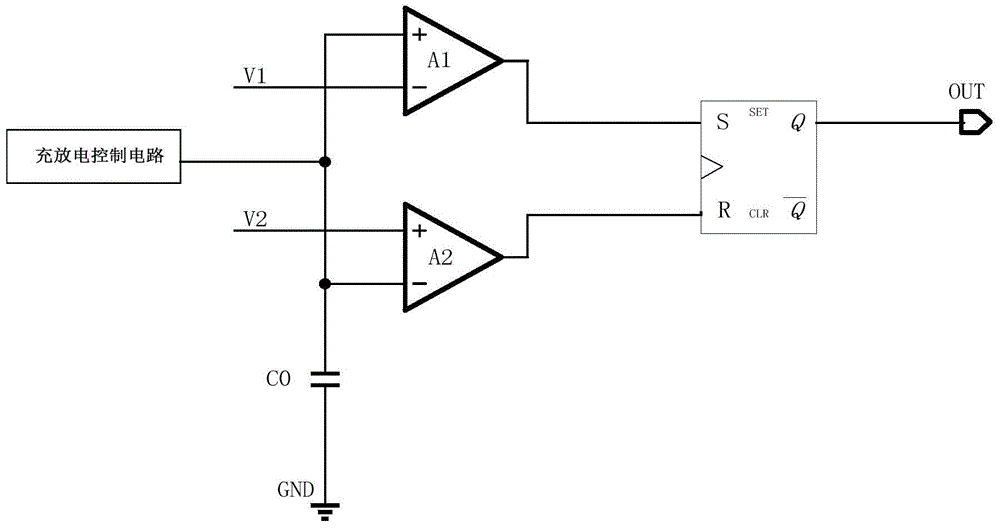
[0004] Traditional RC oscillators are widely used, but there are also some disadvantages: since there are two flipping voltages V1 and V2 in the circuit, the circuit needs two operational amplifiers A1 and A2 as comparators, which will increase the circuit The area and cost increase the complexity of the circuit structure, and the difference in the offset voltage of the two comparators will cause the deviation of the oscillator output frequency

Method used


Image

  • CMOS oscillator
  • CMOS oscillator
  • CMOS oscillator

Examples


Embodiment Construction

[0017] Below in conjunction with accompanying drawing, describe technical scheme of the present invention in detail:

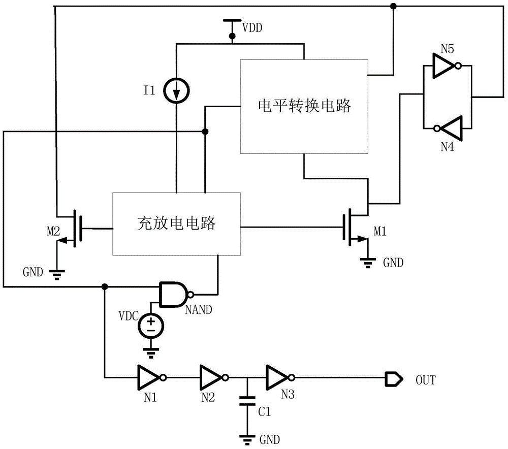
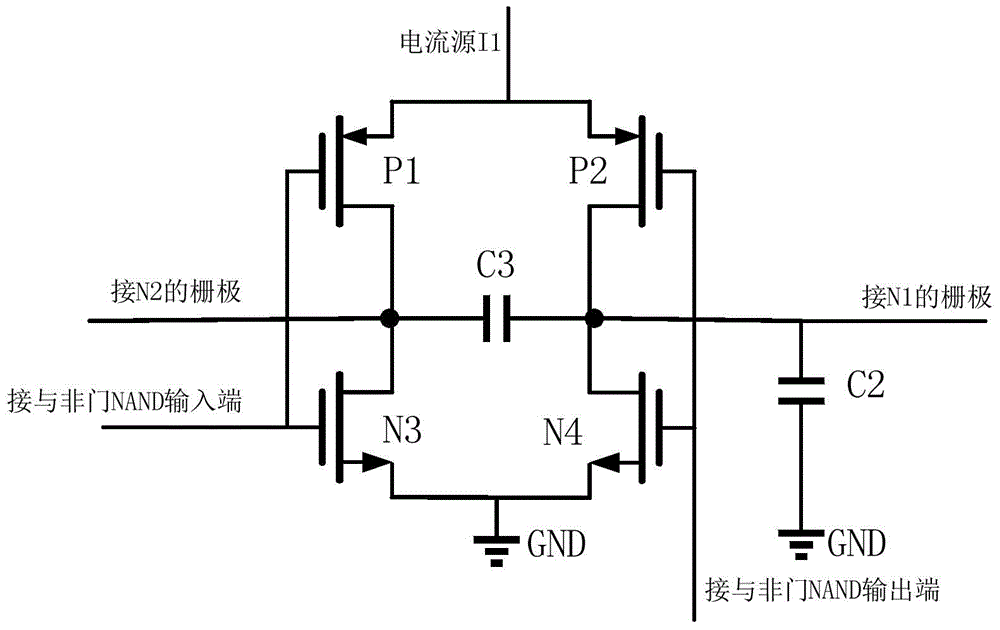
[0018] A CMOS oscillator proposed by the present invention, such as figure 2 As shown, it includes a level conversion circuit, a charging and discharging circuit, a current source I1, a first inverter N1, a second inverter N2, a third inverter N3, a fourth inverter N4, and a fifth inverter N5. , a first NMOS transistor N1, a second NMOS transistor N2, a NAND gate NAND, a DC power supply VDC and a first capacitor C1; wherein, the power input terminal of the level conversion circuit is connected to the power supply VDD, and its first input terminal is connected to The drain of the second NMOS transistor N2, the output terminal of the fifth inverter and the input terminal of the fourth inverter, the second input terminal of which is connected to the drain of the first NMOS transistor N1 and the input terminal of the fifth inverter and the output terminal of the...


PUM


Abstract

The invention, which belongs to the technical field of the analogue integrated circuit, particularly relates to a CMOS oscillator. According to the invention, the pumping characteristic of the capacitor is used and the traditional resistor-capacitor charging and discharging process is replaced; and a way of combination of level conversion with capacitor pumping is employed and the high-speed oscillator characteristic is realized easily. The circuit structure is simple; and the traditional oscillator circuit area with the operational amplifier is reduced and the cost is lowered. Meanwhile, a bistable circuit is introduced and is combined with a level conversion circuit. On the basis of the characteristic of low delay of the level conversion circuit, the response can be started rapidly when the power is on, thereby substantially shortening the starting time of the oscillator. The provided scheme is especially suitable for a high-frequency CMOS oscillator.

Description

technical field [0001] The invention belongs to the technical field of analog integrated circuits, and in particular relates to a CMOS oscillator. Background technique [0002] Oscillator (English: Oscillator), referred to as OSC, is an electronic device used to generate repetitive electronic signals (usually sine waves or rectangular waves). The various oscillating signals generated by it can provide various timing, switch control and signal Various modulations, etc., have become key functional modules in analog and digital circuit systems, and have an important impact on the performance of digital and analog signal processing. With the maturity of semiconductor CMOS technology, CMOS oscillators develop rapidly and gradually replace traditional oscillators. [0003] Oscillators are mainly divided into RC oscillators, LC oscillators, and crystal oscillators according to different circuit structures. figure 1 Shown is a traditional RC oscillator structure block diagram, inc...

Claims


Application Information

Patent Timeline
IPC IPC(8): H03K3/012
Inventor 方健梁湛周义明李桂英沈逸骅
Owner UNIV OF ELECTRONICS SCI & TECH OF CHINA
Learn More