Broaching machine feeding plate

A technology of feeding plate and sliding plate, which is applied in the direction of clamping, supporting, positioning devices, etc., can solve the problems of poor product structure uniformity, low pass rate, and workpiece surface damage, so as to achieve good product structure uniformity, improve production efficiency, and improve consistent effect

Active Publication Date: 2015-09-23
重庆成俊工贸有限公司
View PDF8 Cites 0 Cited by
  • Summary
  • Abstract
  • Description
  • Claims
  • Application Information

AI Technical Summary

Problems solved by technology

[0002] The tooth drawing process includes two processes of initial drawing and finishing drawing. The initial drawing refers to broaching the gear sleeve blank with no teeth in the inner hole, and the finishing drawing refers to correcting the gear sleeve with teeth in the inner hole to meet the product technical requirements. The feeding plate is a tool used to install the workpiece on the broaching machine table. When the traditional feeding plate is loaded into the workpiece, the workpiece can move freely in any direction for 0-3mm, that is, the circumferential direction and radial direction are not positioned, so The workpiece can move and rotate freely within a certain range. When the gear sleeve is fine-drawn, since the feeding plate has no positioning function for the gear sleeve, it is impossible to guarantee the consistency of the relative position of the workpiece on the workbench during each processing, resulting in processing The finished products have poor structural uniformity and a low pass rate. Usually, it is necessary to manually align and install the gear sleeves on the teeth of the broach. During the downward process of the broach, the workpiece still needs to be supported to prevent it from tilting until the broach goes down to the workbench. In the process of fine drawing, the waterproof safety door cannot be closed, so the traditional feeding plate cannot realize the automation of fine drawing, the production efficiency is low, and the risk factor is high; at the same time, the metal chips generated during processing are easily mixed between the feeding plate and the workbench, so again When the workpiece is pushed onto the workbench, it will have strong friction with the bottom surface of the workpiece, and the iron filings will also cause indentations on the surface of the workpiece under the action of huge pressure during tooth pulling, causing damage to the surface of the workpiece

Method used


Image

  • Broaching machine feeding plate
  • Broaching machine feeding plate

Examples


Embodiment Construction

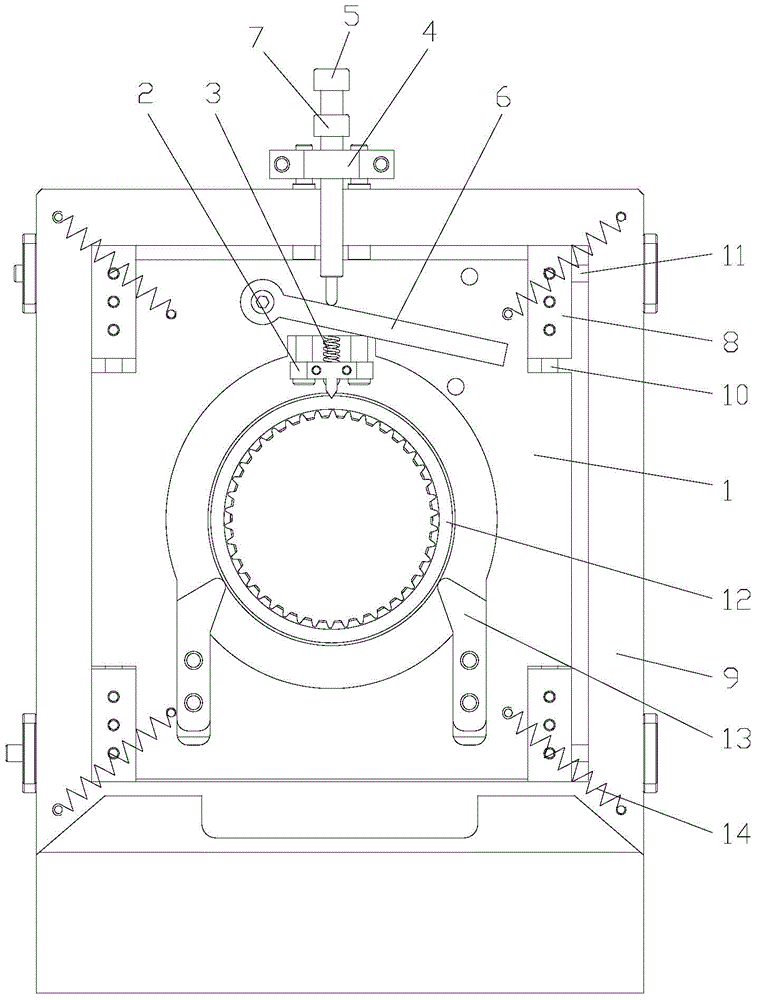
[0016] figure 1 It is a structural schematic diagram of the present invention, figure 2 for figure 1 As shown in the figure: the feeding plate of the broaching machine in this embodiment includes a base 9, a transition piece 8, a first positioning rod 10, a second positioning rod 11, a slide plate 1, a clamping positioning mechanism and a Chip removal block 15; the slide plate 1 is slidably connected to the transition piece 8 through the first positioning rod 10 along the lengthwise direction of the first positioning rod 10, and the transition piece 8 is connected to the transition piece 8 through the second positioning rod 11 along the second positioning rod 11. The longitudinal single degree of freedom is slidably connected to the base 9, and the first positioning rod 10 and the second positioning rod 11 are perpendicular to each other; the slide plate 1 is provided with a vertically penetrating cavity for accommodating the workpiece 12; the clamping positioning The mecha...


PUM


Abstract

The invention discloses a broaching machine feeding plate which comprises a base, transition pieces, first locating rods, second locating rods, a sliding plate, a clamping and locating mechanism and a chip removing block fixed on the base. The clamping and locating mechanism can be used for clamping and locating a workpiece in an accommodating cavity of the sliding plate; the workpiece is located to a certain extent in the circumference direction of the workpiece, and rotation of the workpiece is limited under the condition that horizontal moving of the workpiece is allowed, so that consistency of the relative position of the workpiece on a workbench is improved, and machined products are good in structure uniformity and high in yield; the workpiece does not need to be manually held, automation of finish broaching is facilitated, and production efficiency is improved; a waterproof safety door can be closed in the machining process, and safety can be improved; metal chips between the workpiece and the workbench can be automatically removed in the moving process, friction to the surface of the workpiece is reduced, and damage to the surface of the workpiece is lowered.

Description

technical field [0001] The invention relates to a tooling, in particular to a feeding plate for a broaching machine. Background technique [0002] The tooth drawing process includes two processes of initial drawing and finishing drawing. The initial drawing refers to broaching the gear sleeve blank with no teeth in the inner hole, and the finishing drawing refers to correcting the gear sleeve with teeth in the inner hole to meet the product technical requirements. The feeding plate is a tool used to install the workpiece on the broaching machine table. When the traditional feeding plate is loaded into the workpiece, the workpiece can move freely in any direction for 0-3mm, that is, the circumferential direction and radial direction are not positioned, so The workpiece can move and rotate freely within a certain range. When the gear sleeve is fine-drawn, since the feeding plate has no positioning function for the gear sleeve, it is impossible to guarantee the consistency of t...

Claims


Application Information

Patent Timeline
IPC IPC(8): B23Q3/06B23Q11/00B23F23/06B23F23/00
CPCB23F23/00B23F23/06B23Q3/062B23Q11/00
Inventor 胡军高福臣颜学惠王兴胡成俊舒义蓉颜欢幸定军蔡屏萍
Owner 重庆成俊工贸有限公司
Why Eureka
Try Eureka