Quenching method of die and manufacture method of die

A mold and mold heating technology, applied in the direction of manufacturing tools, heat treatment equipment, furnaces, etc., can solve problems such as easy cracks, achieve the effect of suppressing cracks and maintaining toughness

Active Publication Date: 2015-09-23
HITACHI METALS LTD
View PDF6 Cites 1 Cited by
  • Summary
  • Abstract
  • Description
  • Claims
  • Application Information

AI Technical Summary

Problems solved by technology

In addition, since the surface of the mold is also engraved to form the shape of the product (molded product), stress concentrates

Method used


Image

  • Quenching method of die and manufacture method of die
  • Quenching method of die and manufacture method of die
  • Quenching method of die and manufacture method of die

Examples


Example Embodiment

[0039] Example

[0040] Experimental points
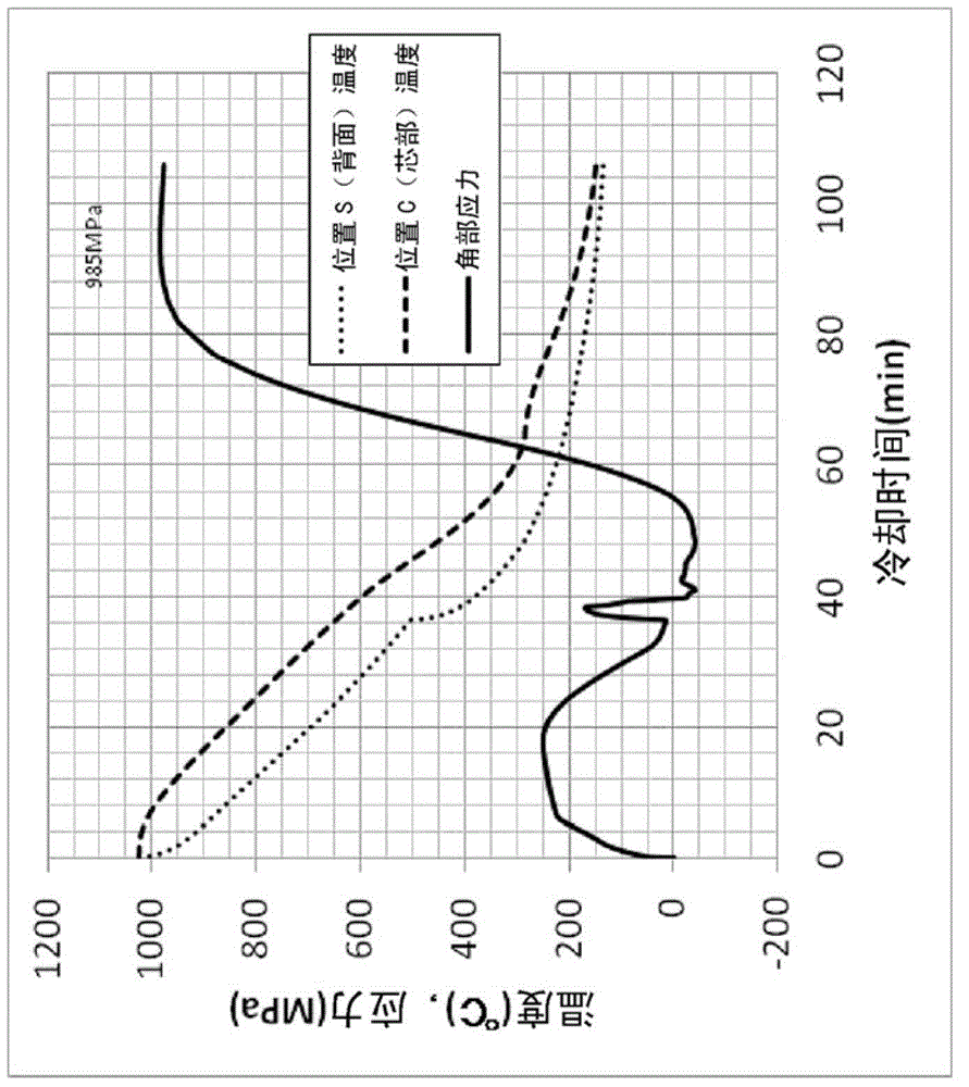
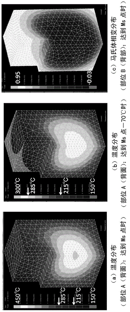
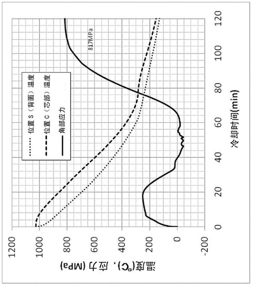
[0041] The hot working tool steel of Japanese JIS-SKD61 improved material is used as the raw material to make a square of 300mm×300mm×300mm. Milling is performed on the entire surface of the block. The martensite transformation point (Ms point) of this raw material is 285°C. Next, the block was processed to form a concave groove with a depth of 100 mm and a width of 50 mm corresponding to the product shape surface of the mold, thereby forming a groove that imitated the shape of the mold. Figure 7 Sample for quenching. The corner of the groove bottom was processed so that the R (radius of curvature) of the corner was 1 mmR on one side and 3 mmR on the side opposite to the side. In addition, from the center of the groove bottom toward the back of the sample, the position C (that is, the core of the sample) at a depth of 90 mm and the position S (that is, the actual back of the sample) at a depth of 195 mm In the center of the ), an...


PUM


Abstract

The invention provides a quenching method of a die and a manufacture method of a die which can restrain cracks of product shape surfaces of dies. In the quenching method, a die is heated to the quenching temperature of an austenite area and then cooled, so that the organization of the die is subject to martensite phase transformation. The cooling is performed in such a manner that when the temperature of an area A with the highest temperature of the opposite surface of the product shape surface of the die, namely the back surface of the die, at least passes through the temperature range from martensite phase transformation point to the martensite phase transformation point -70 DEG C, an area B with the highest temperature in the die is made to transfer to the back surface side of the die in part of or all the temperature range. Preferably, when the temperature of the area B passes through the temperature range from the martensite phase transformation point +50 DEG C to the martensite phase transformation point, the area B is cooled at the speed of 3.0 DEG C/min. The invention also provides the manufacture method of a die which is used for tempering of the die quenched with the quenching method of a die.

Description

technical field [0001] The invention relates to a quenching method of a mold and a manufacturing method of the mold. Background technique [0002] In the quenching process of the mold in which the mold is heated to the quenching temperature in the austenite region and then cooled to allow the structure of the mold to undergo a martensitic transformation, the cooling rate of the surface of the mold is usually faster than that of the inside of the mold ( That is to say, the surface of the mold undergoes martensitic transformation before the interior of the mold). Therefore, after the martensitic transformation is first performed on the surface of the mold, the martensitic transformation is carried out later in the mold, so that the surface of the mold that has almost completed the martensitic transformation undergoes thermal contraction as cooling progresses. , on the other hand, phase change expansion takes place inside the mold, thereby causing tensile stress on the surface...

Claims


Application Information

Patent Timeline
IPC IPC(8): C21D1/18C21D9/00
Inventor 西田纯一
Owner HITACHI METALS LTD
Why Eureka
Try Eureka