Eureka AIR delivers breakthrough ideas for toughest innovation challenges, trusted by R&D personnel around the world.

Multifunctional fluid engine

An engine and multi-functional technology, applied in the fields of wind energy, airflow as kinetic energy, water energy and steam flow, it can solve problems such as difficulty in improving efficiency, and achieve the effect of simple structure and high efficiency.

Active Publication Date: 2015-09-23
京电中能(北京)能源有限公司
View PDF4 Cites 7 Cited by
  • Summary
  • Abstract
  • Description
  • Claims
  • Application Information

AI Technical Summary

Problems solved by technology

[0002] For a long time, the structure and shape of the driving parts of steam turbines, water turbines, and wind power generators have been kept in the traditional way, and it is difficult to improve the efficiency

Method used


Image

  • Multifunctional fluid engine
  • Multifunctional fluid engine

Examples


Embodiment Construction

[0013] method one"

[0014] One-stage drive multifunctional fluid engine 【1】

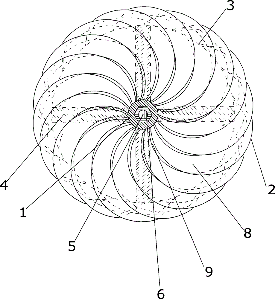
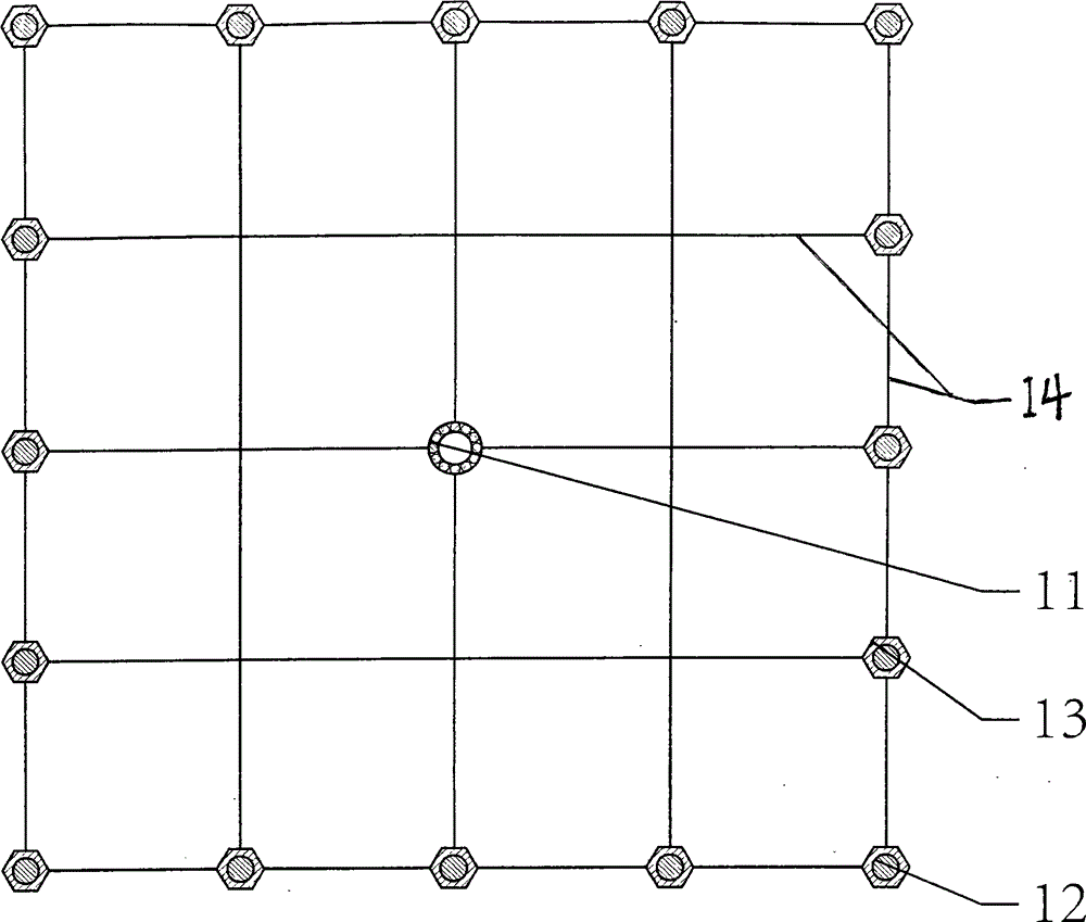
[0015] The utility model relates to a multifunctional generating machine for using fluid as kinetic energy, and is especially suitable for generating machines for steam flow, water energy, wind energy, and air flow as kinetic energy. It includes: bushing (1), concentrating drive vane (2), inlet neck (3), supporting drive vane (4), shaft (5), nut (6), flange frame (7), bearing (11 ).

[0016] A bearing (11) is respectively arranged in the middle of the two ends of the hurdle frame (7), and a movable shaft (5) is arranged in the bearing (11). The tail-stage bushing (1) is fixed with a tail-stage nut (6); between the tail-stage bushing (1) and the outlet of the inlet neck (3) there are multiple flow-concentrating drive vanes (2) The tilting head of the flow driving blade (2) is designed at the outlet of the inlet neck (3), and there is a gap between the blades, which is a fluid flow channel. Its fun...


PUM


Abstract

An engine using a fluid as kinetic energy is provided. A movable shaft is arranged on a flange rack, and a shaft sleeve is fixed on the shaft through a nut; a plurality of converging and driving blades which tilt towards one end are arranged between the shaft sleeve and an outlet of an inlet neck, so that a one-stage driving type is formed, and a plurality of such one-stage driving types can also form a multi-stage type; under the influence of front-and-back pressure difference of the inlet neck, a part of the fluid with certain pressure expands forward and flows out of blade clearance passages of a supporting section of a fluid density rarefying chamber; the fluid density rarefying chamber is formed by a driving impeller with the converging and driving blades which tilt towards one end serving as the radius and is provided with an inlet passage and an outlet passage; the other part of the fluid expands around and flows out of blade clearance passages of an all-around tilting section so as to increase the effect of acting force; during the flowing process, acting force is exerted on the converging and driving blades; and at the same time, due to the supporting function of the supporting section, inertia potential energy of a telecentric section and the inlet neck exerts effects, and the telecentric section and the inlet neck together drive the converging and driving blades to perform circular movement and drive the shaft sleeve and the shaft to rotate, so that mechanical power which is output to the external is obtained on the shaft of the multifunctional fluid engine.

Description

【Technical field】 [0001] The invention relates to a generator for using fluid as kinetic energy, and is particularly suitable for generators using steam, water, wind and air as kinetic energy and a process method thereof. 【Background technique】 [0002] For a long time, the structure and shape of the driving parts of steam turbines, water turbines, and wind power generators have been kept in the traditional way, and it is difficult to improve the efficiency. [0003] The object of the present invention is to provide a machine for generating kinetic energy from a fluid in order to eliminate the above-mentioned disadvantages of the technology currently used. 【Content of invention】 [0004] A kind of engine that uses fluid as kinetic energy, especially suitable for steam flow, water energy, wind energy, and airflow as kinetic energy: a fluid with a certain pressure first flows through the engine with a pressure difference between the front and rear of the inlet neck The inle...

Claims


Application Information

Patent Timeline
Patent Type & Authority Applications(China)
IPC IPC(8): F01D1/20F01D5/34F03B3/00F03B3/12F03D1/02F03D1/06
CPCY02E10/20Y02E10/72
Inventor 从宏锦
Owner 京电中能(北京)能源有限公司
Why Eureka
Eureka Blog
Learn More