Roller bearing

A technology of roller bearings and bearings, applied in the direction of roller bearings, bearing components, shafts and bearings, to achieve the effects of low friction, avoiding temperature rise, and high service stability

Inactive Publication Date: 2015-09-23
LANZHOU INST OF CHEM PHYSICS CHINESE ACAD OF SCI
View PDF12 Cites 6 Cited by
  • Summary
  • Abstract
  • Description
  • Claims
  • Application Information

AI Technical Summary

Problems solved by technology

[0005] In view of the above problems, the object of the present invention is to provide a roller bearing, especially a roller bearing used under heavy loads, which needs to bear high axial load or combined shaft and radial load, which not only has an improved roller end stop Pushing the lubrication state and wear resistance of the contact area can effectively avoid the bearing friction and wear problems caused by hard particles such as grinding debris or external pollutants, and further improve the roller bearings in harsh conditions such as high speed, heavy load, impact load and sand and dust. Service performance under conditions

Method used


Image

  • Roller bearing
  • Roller bearing
  • Roller bearing

Examples


Embodiment 1

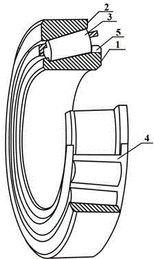
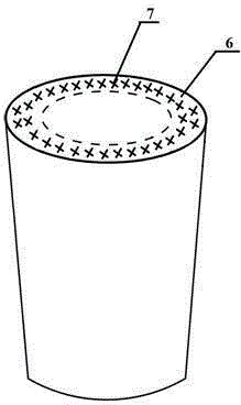
[0022] Such as figure 1 , 2 As shown, the roller bearing includes an inner ring 1 with a raceway on the outer circumference, an outer ring 2 with a raceway on the inner circumference, a roller 3 between the raceway of the inner ring 1 and the raceway of the outer ring 2, a cage 4 and The thrust structure 5, the thrust contact area 6 on the end surface of the roller 3 is a compound lubricating structure, the compound lubricating structure is composed of a solid lubricating coating and a surface micro-texture 7, wherein the surface micro-texture 7 is uniformly distributed micro pits array.

[0023] The thrust structure 5 is a rib or a retaining ring.

[0024] The shape of the pits in the micro pit array is one of circle, ellipse, triangle and quadrangle or a combination thereof.

[0025] The area density of micro-pits is less than 65%, and the depth is greater than 5 μm.

[0026] The solid lubricating coating includes an amorphous carbon layer and a transition layer, the tot...

Embodiment 2

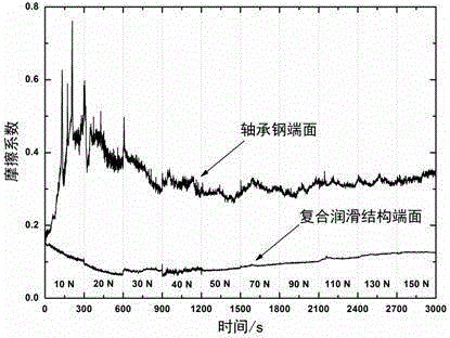
[0030] image 3 It is the change diagram of the friction coefficient between the tapered roller end face and the bearing steel roller end face of the present invention. The base material of the roller is GCr15 bearing steel, the diameter of the large end of the roller is 10 mm, and the micro-texture in the compound lubrication structure is a circular micro-pits array, the diameter of the pits: 200 μm, the density Dt : 25%, pit depth 5~7 μm. The solid lubricating coating is a Cr-doped amorphous carbon layer, the transition layer is Cr, and the total thickness of the coating is 2.5 μm. The SRV friction testing machine was used to test the friction coefficient change of the GCr15 bearing steel roller end face and the roller end face with compound lubrication structure. The test conditions were: amplitude 1 mm, frequency 25 Hz, load 10-150 N, lubricant PAO-10, friction The dual is a bearing steel disc to simulate the contact between the roller end face and the raceway rib.

[...


PUM


Abstract

The invention discloses a roller bearing, which comprises an inner ring with a raceway on the outer periphery, an outer ring with a raceway on the inner circumference, a roller between the inner ring raceway and the outer ring raceway, a cage and a thrust structure. A thrust contact region on the roller end face is a composite lubricating structure which comprises a solid lubricating coating and a surface microtexture, wherein the surface microtexture is a uniformly distributed micro-pit array. The roller bearing provided by the invention has the advantages of anti-jamming capability enhancement, low friction and high service stability, and is applicable to efficient transmission of a spindle mechanism bearing axial or axial-radial joint load under harsh conditions of high speed, heavy load, impact load and dust.

Description

technical field [0001] The invention relates to a roller bearing, especially the roller bearing used under heavy load, which needs to bear high axial load or combined axial and radial load. Background technique [0002] The heavy-duty roller bearings used in machinery such as the main shaft of large-scale wind turbines or the main shaft of high-speed railway locomotives must not only meet the radial load, but also need to bear a certain axial load. This type of bearing often has a thrust design, that is, a rib or a retaining ring is designed on the inner ring or (and) outer ring of the bearing to prevent the axial movement of the roller. Different from the rolling contact between the rolling surface of the roller and the raceway, the thrust contact area of ​​the end surface of the bearing roller and the rib (ring) is a sliding contact. When the bearing lubrication is poor due to harsh working conditions such as start-stop, heavy load or impact load, the lubrication state be...

Claims


Application Information

Patent Timeline
Patent Type & Authority Applications(China)
IPC IPC(8): F16C19/36F16C33/34F16C33/36
CPCY02T10/86
Inventor 胡丽天丁奇汤金柱张广安
Owner LANZHOU INST OF CHEM PHYSICS CHINESE ACAD OF SCI
Why Eureka
Try Eureka