Cement processing drying device

A technology for drying equipment and cement, applied in the field of cement processing, can solve problems such as difficulty in operation and quality control, deterioration of mill operating conditions, and impact on the quality of milled products, so as to prolong residence time, improve heat exchange efficiency, and improve motor speed. suitable effect

Inactive Publication Date: 2015-09-23
郑鹏飞
View PDF0 Cites 0 Cited by
  • Summary
  • Abstract
  • Description
  • Claims
  • Application Information

AI Technical Summary

Problems solved by technology

The more moisture in the grinding material, the higher the moisture content in the mill, and the fine-grained material will adhere to the grinding body, liner and compartment plate, which will reduce the grinding efficiency. Moreover, if the moisture in the grinding material is too high , it will inevitably deteriorate the working conditions of the mill, which will bring difficulties to the operation and quality control. In addition, the mixing ratio of the materials fed into the mill will be changed by the fluctuation of the moisture in the materials, so that the grinding The quality of the product is also affected accordingly. The drying process of using a dryer to remove excess moisture from the material is an indispensable and important link in cement production. Therefore, a cement processing drying equipment is proposed to solve the above problems.

Method used


Image

  • Cement processing drying device
  • Cement processing drying device

Examples


Embodiment Construction

[0012] The following will clearly and completely describe the technical solutions in the embodiments of the present invention with reference to the accompanying drawings in the embodiments of the present invention. Obviously, the described embodiments are only some, not all, embodiments of the present invention. Based on the embodiments of the present invention, all other embodiments obtained by persons of ordinary skill in the art without making creative efforts belong to the protection scope of the present invention.

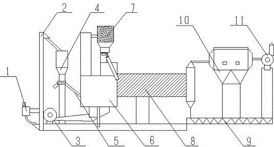
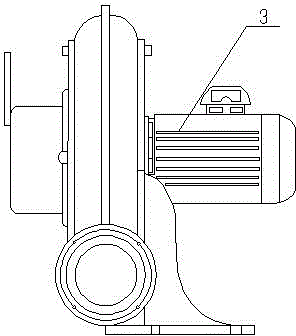
[0013] see Figure 1~2 , a cement processing and drying equipment, including a coal crusher 1, a hoist 2, a high-pressure fan 3, a coal bunker 4, a coal feeding electric vibrator 5, a high-temperature fluidized furnace 6, a feeding device 7, a lifting plate 8, a discharge Reamer 9, dust remover 10 and dust-proof blower 11; Described coal crusher 1 is arranged on elevator 2 side, and the outlet of coal crusher 1 is provided with broken coal hopper; Described el...


PUM


Abstract

The invention discloses a cement processing drying device. The device comprises a coal crusher, an elevator, a high-pressure draught fan, a coal bunker, a coal feeding electric vibrating machine, a high-temperature fluidized bed furnace, a feeding device, a lifting board, a discharging reamer, a dust remover and a dustproof draught fan. The coal crusher is disposed on one side of the elevator, and a crushed coal bucket is arranged at an outlet of the coal crusher; the coal bunker is disposed at one end of the high-temperature fluidized bed furnace; the coal feeding electric vibrating machine is arranged at one end of the coal bunker; the high-temperature fluidized bed furnace is arranged on one side of the lifting board; the feeding device is installed at one end of the high-temperature fluidized bed furnace; the high-pressure draught fan is arranged at one end of the high-temperature fluidized bed furnace; the discharging reamer is arranged at one end of the dust remover; and the dustproof draught fan is arranged on one side of the dust remover. The heat efficiency of the lifting board of the cement processing drying device is high, the rotation speed of a motor is appropriate, the cooling capacity of a drying machine is high, and the cement processing drying device has good economic benefits and social benefits and is suitable for application and popularization.

Description

technical field [0001] The invention relates to the technical field of cement processing, in particular to cement processing drying equipment. Background technique [0002] With the development of modern buildings and the construction of roads, the demand for cement is increasing. The indispensable step in the process of cement processing is drying. The application of dryers in the cement industry is in the cement industry. When using In dry production, various water-containing substances such as raw materials, coal and mixed materials need to be dried, and in wet production, coal and mixed materials also need to be dried, so as to ensure the normal operation of grinding. These all need a dryer to complete. The moisture content of the material entering the mill, the quality of the material leaving the mill and the operation of the mill all have a great influence on the output of cement. The more moisture in the grinding material, the higher the moisture content in ...

Claims


Application Information

Patent Timeline
Patent Type & Authority Applications(China)
IPC IPC(8): F26B11/04F26B21/00F26B25/00
Inventor 郑鹏飞
Owner 郑鹏飞
Why Eureka
Try Eureka