
Seal friction compensation method for hydrogen environment material performance testing device

A material performance and testing device technology, applied in the field of sealing friction compensation, can solve problems such as low precision and failure to reflect friction changes, and achieve the effect of improving measurement accuracy

Active Publication Date: 2018-03-02
HEFEI GENERAL MACHINERY RES INST
View PDF6 Cites 0 Cited by
  • Summary
  • Abstract
  • Description
  • Claims
  • Application Information

AI Technical Summary

Problems solved by technology

This method cannot reflect the change of test state (temperature, loading waveform, loading rate) and the friction change caused by the aging of the sealing ring, so the accuracy is not high, and it needs to be improved urgently

Method used

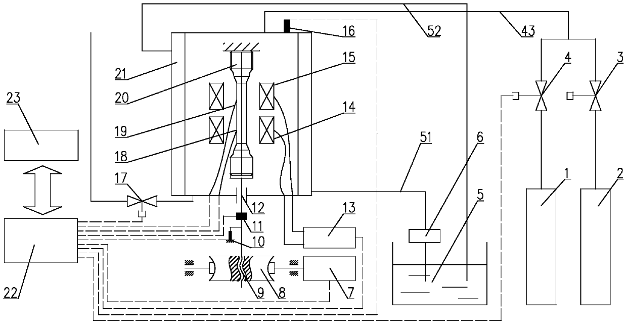
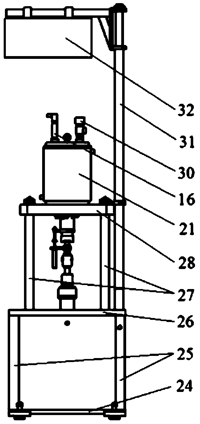
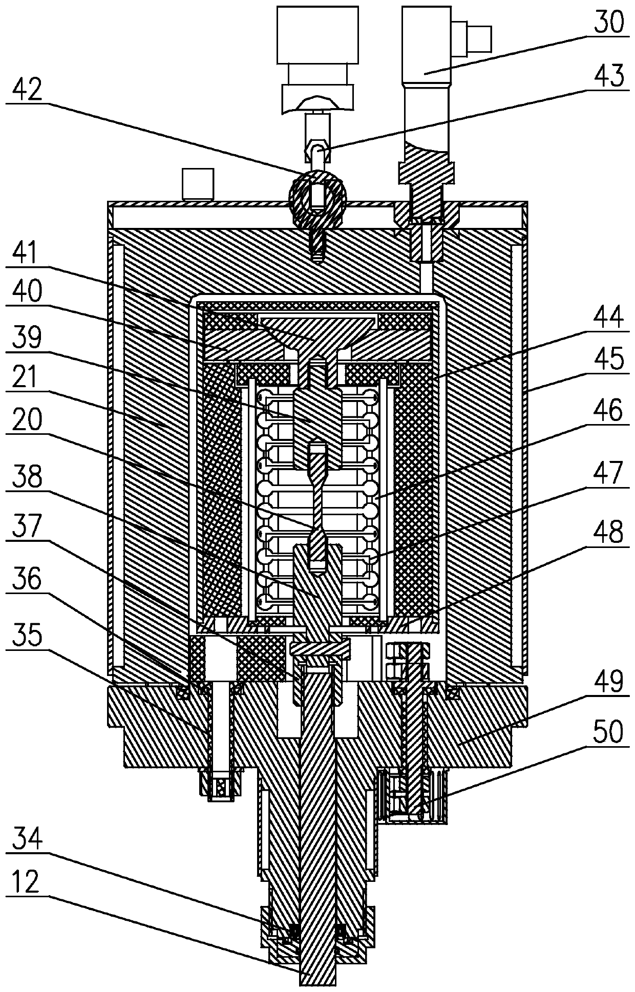

Image

  • Seal friction compensation method for hydrogen environment material performance testing device
  • Seal friction compensation method for hydrogen environment material performance testing device
  • Seal friction compensation method for hydrogen environment material performance testing device

Examples


Embodiment 1

[0091] Carry out ramp loading and holding experiments.

[0092] During the experiment, the friction force is compensated by the method proposed in the present invention to obtain the sample load. Implementation steps include:

[0093] 1. Set the test parameters without clamping the sample.

[0094] 2. After the test device reaches the set test parameters, start ramp loading, and the measured load curve is recorded as the seal friction curve, such as Figure 8 Curve C in ns shown.

[0095] 3. Clamp the sample and set the test parameters.

[0096] 4. After the test device reaches the set test parameters, the ramp load is started, and the measured load curve is recorded as the combined load curve, such as Figure 8 Middle curve C ws shown.

[0097] 5. From combined load curve C ws Subtract the expanded seal friction curve C from ns get as Figure 8 Curve C shown in s , which is the load curve of the sample.

[0098] Example 1 shows that the sealing friction force is a...

Embodiment 2

[0100] Carry out the cosine wave loading experiment.

[0101] During the experiment, the friction force is compensated by the method proposed in the present invention to obtain the sample load. Implementation steps include:

[0102] 1. Set the test parameters without clamping the sample.

[0103] 2. After the test device reaches the set test parameters, start cosine wave loading, and the measured load curve is recorded as the seal friction curve, such as Figure 9 Curve C in ns shown.

[0104] 3. Clamp the sample and set the test parameters.

[0105] 4. After the test device reaches the set test parameters, start cosine wave loading, and measure the load curve as the combined load curve, such as Figure 9 Middle curve C ws shown.

[0106] 5. From combined load curve C ws Subtract the expanded seal friction curve C from ns get as Figure 9 Curve C shown in s , which is the load curve of the sample.

[0107] Example 2 shows that the sealing friction force is alternat...


PUM


Abstract

The invention relates to a sealing friction compensating method for a material performance testing device in a hydrogen environment, which includes the following steps: S1, without clamping the sample, setting tester parameters according to the test requirements, including temperature and load; S2, starting Test, measure the sealing friction curve; S3, clamp the sample, set the tester parameters according to the test requirements, including temperature and load; S4, conduct the test, measure the combined load curve; S5, use the sealing friction obtained in S2 The force curve is periodically expanded according to the combined load curve in S4, and then the expanded seal friction curve is subtracted from the combined load curve in S4 to obtain the load curve of the sample. This method is not only applicable to the compensation of sealing friction caused by reaction temperature, gas pressure and aging of sealing ring during unidirectional tensile loading performance test, but also especially suitable for the compensation of sealing friction caused by various factors such as reaction alternating load. The method greatly improves the measurement precision of the friction force and the load of the sample.

Description

technical field [0001] The invention relates to the technical field of material performance testing methods, in particular to a sealing friction compensation method for a hydrogen environment material performance testing device. Background technique [0002] The hydrogen environment material performance test device is an important test equipment for testing the performance of materials in a hydrogen environment, establishing a corresponding material database, and studying the mechanism of hydrogen damage, etc., to study how to compensate the impact of the seal friction of the test equipment on the load measurement of the sample during the test, Improving the measurement accuracy of the load on the sample is of great significance for the material performance testing device. [0003] At present, the commonly used method to overcome the influence of sealing friction on the load measurement of the sample is represented by Changchun Mechanical Science Research Institute Co., Ltd....

Claims


Application Information

Patent Timeline
Patent Type & Authority Patents(China)
IPC IPC(8): G01N3/08G01N3/02G01N3/04
Inventor 陈学东刘孝亮王冰范志超庄庆伟
Owner HEFEI GENERAL MACHINERY RES INST
Learn More