Improved high-resolution SAR (synthetic aperture radar) imaging self-focusing method

A high-resolution, self-focusing technology, which is applied in the field of improved high-resolution SAR imaging self-focusing and motion error compensation of airborne SAR imaging, can solve the problems of large amount of calculation, poor performance of motion error estimation, and low signal-to-noise ratio. problem, to achieve good focusing effect, high robustness and accuracy

Active Publication Date: 2015-09-23
XIDIAN UNIV
View PDF5 Cites 33 Cited by
  • Summary
  • Abstract
  • Description
  • Claims
  • Application Information

AI Technical Summary

Problems solved by technology

Although the method based on image migration is easy to implement, when estimating complex motion errors in high-resolution SAR imaging, the estimation accuracy of motion errors cannot meet the requirements; the phase gradient self-focusing method is a motion compensation process in SAR imaging The most commonly used self-focusing method, this method can accurately estimate any form of motion error for data containing isolated scattering points, but for data with low signal-to-noise ratio and no obvious strong scattering points in the scene, such as The motion error estimation performance of this method is also poor for the data obtained in desert and sea conditions; the calculation amount of the method based on the cost function is generally relatively large, and this method is easily affected by the characteristics of the cost function itself. less than good focus

Method used


Image

  • Improved high-resolution SAR (synthetic aperture radar) imaging self-focusing method
  • Improved high-resolution SAR (synthetic aperture radar) imaging self-focusing method
  • Improved high-resolution SAR (synthetic aperture radar) imaging self-focusing method

Examples


Embodiment Construction

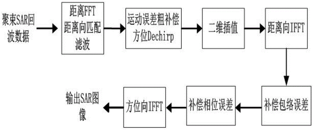
[0027] refer to figure 1 , is a schematic flow chart of an improved high-resolution SAR imaging self-focusing method of the present invention, and the improved high-resolution SAR imaging self-focusing method includes the following steps:

[0028] Step 1. After performing range pulse compression on the radar echo signal received by the SAR radar antenna, the range pulse pressure radar echo signal is obtained in, Indicates the azimuth fast time, t m Indicates the azimuth slow time.

[0029] The specific process of step 1 is:

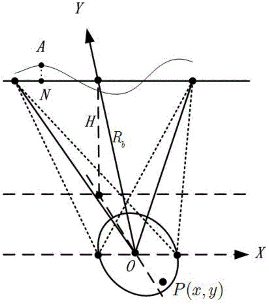
[0030] refer to figure 2 , is the geometric model of the SAR radar in the side-looking spotlight mode, select the center point O of the scene as the coordinate origin, and establish a plane Cartesian coordinate system. The direction of the SAR) center is the positive direction of the Y axis, P is any point target in the scene, and its coordinates are (x, y), the ideal track of the SAR radar is along the positive direction of the X axis at the spee...


PUM


Abstract

The invention discloses an improved high-resolution SAR (synthetic aperture radar) imaging self-focusing method. The method mainly comprises the following steps that: range pulse compression, preliminary movement compensation and range direction FFT are sequentially performed on radar echo signals, so that movement compensated radar echo signals and the simplified form of the movement compensated radar echo signals can be obtained sequentially; the simplified form of the movement compensated radar echo signals is multiplied by an azimuth Dechirp function; two-dimension interpolation is performed along the range and azimuth directions respectively; after two-dimension interpolated radar echo signals are obtained, IFFT is performed along the range direction, so that phase history-domain data can be obtained; envelope error compensation of the phase history-domain data can be accomplished through adopting an image shift SAR self-focusing algorithm, the phase error of the phase history-domain data of which the envelope error compensation has been completed can be solved through utilizing a conjugate gradient algorithm; after the phase history-domain data of which the envelope error compensation and phase error compensation have been completed are obtained, IFFT is performed along the azimuth direction, so that a high-resolution SAR image with an excellent focusing effect can be obtained.

Description

technical field [0001] The invention belongs to the technical field of radar imaging, in particular to an improved self-focusing method for high-resolution SAR imaging, which is suitable for motion error compensation of airborne SAR imaging. Background technique [0002] The self-focusing method starts from the data itself, estimates the non-spatial variable phase error data that affects the imaging result, and compensates the non-spatial variable phase error data, so as to obtain good imaging results. [0003] Existing autofocus methods can be roughly divided into three categories, specifically: methods based on image offset, methods based on Phase Gradient Autofocus (PGA) and methods based on cost functions. Although the method based on image migration is easy to implement, when estimating complex motion errors in high-resolution SAR imaging, the estimation accuracy of motion errors cannot meet the requirements; the phase gradient self-focusing method is a motion compensat...

Claims


Application Information

Patent Timeline
Patent Type & Authority Applications(China)
IPC IPC(8): G01S13/90
CPCG01S13/90G01S13/9019
Inventor 梁毅邢孟道别博文曾乐天
Owner XIDIAN UNIV
Why Eureka
Try Eureka