Transmission device for novel differential rotation mop

A technology of rotating mop and transmission device, which is applied in the field of household sanitary ware, which can solve the problems of difficult control of rotation speed, difficult realization of functions, and unreliable structure, etc., and achieve the effects of reducing downforce, fast and compact connection, and reliable structural design

Inactive Publication Date: 2015-09-30
冠达星股份有限公司
View PDF9 Cites 3 Cited by
  • Summary
  • Abstract
  • Description
  • Claims
  • Application Information

AI Technical Summary

Problems solved by technology

This kind of hand-pressed rotary mop and the special dehydration bucket of the hand-pressed rotary mop, but when washing, due to the resistance of water, it needs to provide a greater downward force to drive it, which makes it difficult to realize the function during washing. However, if the speed is too high, water splashes will be splashed out during washing, and the rotation speed is difficult to control
There is also a hand-pressed variable-speed rotary mop on the market. The Chinese patent with the publication number CN203042161U discloses a hand-pressed variable-speed rotary mop, which mainly includes a hand-pressed mop rod and a rotary mop. The rotary mop includes a mop connector and a mop disc. , Cotton yarn fixed disc, star gear, central gear, large toothed disc, the cotton fixed disc is fixed on the mop disc, the connecting shaft on the upper part of the central gear passes through the center hole of the mop disc and is inserted into the mop connector and is connected with the hand-pressed mop rod together. The star gear is rotatably arranged on the mop disc, and the large tooth plate is rotatably arranged on the tray of the central gear and covered on the star gear. The inner ring of the star gear meshes with the central gear, and the outer ring meshes with the large tooth. The disc meshes, and the mop can be cleaned by pressing the mop rod with force, but the structure puts the gear in the mop head, which makes the structure more complicated and unreliable

Method used


Image

  • Transmission device for novel differential rotation mop
  • Transmission device for novel differential rotation mop
  • Transmission device for novel differential rotation mop

Examples


Embodiment Construction

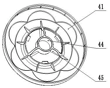
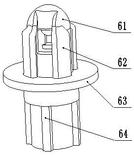
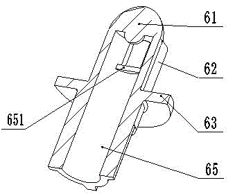
[0038] Such as figure 1 As shown, the present invention is a transmission device for a novel differential rotating mop, which includes a mop rod connector 1, an annular positioning buckle 2, a mop head transmission sleeve 3, a mop rotating disc 4, a cotton yarn fixing disc 5, a transmission Mandrel 6, differential shift fork seat 7, centering gear 8, differential gear 9, internal gear disc 10, centering shaft rod 10A.

[0039] combine figure 2 The schematic cross-sectional view of the overall structure, the upper end of the mop rod connector 1 is screwed and fixedly connected with the mop rod (not shown in the figure), the lower end of the mop rod connector 1 is hinged with the mop head drive shaft sleeve 3 through the hinge bolt 15; the ring positioning buckle 2 The end face is in clearance fit with the upper shoulder of the mop drive shaft sleeve 3, the lower shoulder of the mop head drive shaft sleeve 3 is in clearance fit with the mop rotating disc 4, and the elastic hoo...


PUM


Abstract

The invention discloses a transmission device for a novel differential rotation mop. The device comprises a mop rod connector, an annular positioning buckle, a mop head transmission shaft sleeve, a mop rotation disc, a cotton yarn fixing disc, a transmission mandrel, a differential shifting fork disc seat, a centering gear, a differential gear, an internal gear disc and a centering shaft rod. The mop head transmission shaft sleeve is driven to rotate by driving the mop rod connector to rotate, and then the transmission mandrel is made to rotate through the cooperation of a guiding spline groove and a guiding spline, so that the centering gear is driven to rotate. The internal gear disc, the centering gear, the differential gear, a coupling and a mop shifting fork constitute a speed reduction mechanism to reduce the rotating speed of the mop rotation disc and reduce driving force, and the mop can be cleaned under light pressure. The device has the advantages of being effortless in operation, simple in structure, reliable in centering and stable in rotation.

Description

technical field [0001] The invention relates to the field of household sanitary ware, in particular to a novel rotating mop transmission device for household sanitary ware. Background technique [0002] At present, it has become a mainstream to use a rotary mop to replace the simple mop in the past for cleaning the ground hygiene of the home life or office. The spin mop is a new type of mop, which is light and easy to hold and easy to clean. The spin mop adopts the principle of centrifugal force and can quickly dehydrate. The mop head of the spin mop is made of special microfiber, which has super water absorption performance. The rotary mop can realize the integrated effect of drying and cleaning. [0003] The rotary mop is mainly composed of a mop rod assembly, a mop bucket assembly, and a variable speed drive mechanism. The design of the variable speed drive mechanism is the most critical. A well-designed variable speed drive mechanism can save a lot of materials and gre...

Claims


Application Information

Patent Timeline
Patent Type & Authority Applications(China)
IPC IPC(8): A47L13/20A47L13/24F16H48/12
Inventor 杨建明李宝玉
Owner 冠达星股份有限公司
Why Eureka
Try Eureka