Rotary mop head with differential mechanism

A rotating mop head and mop technology, applied in the field of household sanitary ware, can solve the problems of increased assembly time, difficulty in controlling the rotation speed, and difficult realization of functions, etc., and achieve the effects of optimized transmission structure, reliable structural design, and stable and reliable transmission

Inactive Publication Date: 2015-11-25
冠达星股份有限公司
View PDF8 Cites 1 Cited by
  • Summary
  • Abstract
  • Description
  • Claims
  • Application Information

AI Technical Summary

Problems solved by technology

The Chinese patent with the publication number CN201701166U discloses a centrifugal dehydration rotary mop head. There is no deceleration mechanism arranged on this rotary mop head. When used on a rotary mop bucket with a deceleration device, this mop head and a mop with a deceleration mechanism There is not much difference in the head, but when it is used on the mop bucket without deceleration device, due to the resistance of the water, it needs to provide a greater downforce to drive when it is used, which makes it difficult to realize the function during washing, and If the speed is too high, water will splash out during washing, and the rotation speed will be difficult to control
Therefore, the limitation of this mop head is relatively large, and various rotating mop buckets cannot be generally used
Rotating mop heads with deceleration mechanisms have also appeared on the market at present. Another example is that the Chinese patent with the publication number CN203303001U discloses a new type of mop. The deceleration device contains multiple planetary gears, and the planetary carrier needs to be designed separately to support the planetary gear train. This kind of deceleration device has a complex structure. Although it can reduce the speed, it increases the production cost and increases the assembly time during production due to the large number of parts. Not suitable for the needs of mass production now

Method used


Image

  • Rotary mop head with differential mechanism
  • Rotary mop head with differential mechanism
  • Rotary mop head with differential mechanism

Examples


Embodiment Construction

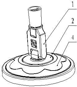
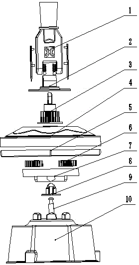
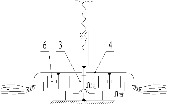
[0027] Such as figure 1 , figure 2 with image 3 As shown, the present invention is a rotary mop head with a differential mechanism, which includes a mop rod connector 1, an annular positioning ferrule 2, a centering gear shaft 3, a mop rotating disc 4, a cotton yarn fixing disc 5, and a differential gear 6 and differential fork ring gear 7. Such as Figure 4 with Figure 5 As shown, the upper end of the mop rod connector 1 is fixedly connected with the mop rod, and the lower end is jointly hinged with the annular positioning ferrule 2 and the centering gear shaft 3 . The inner cavity of the annular positioning ferrule 2 and the centering gear shaft 3 are interference fit. Such as figure 2 As shown, the mop rotating disk 4 is fixed between the annular positioning ferrule 2 and the centering gear shaft 3, and two positioning shafts are symmetrically distributed along the axis inside it. There are two differential gears 6, which are respectively sleeved on two positioni...


PUM


Abstract

The invention discloses a rotary mop head with a differential mechanism, comprising a mop pole connector, a circular positioning ferrule, a centering gear shaft, a mop rotary disc, a spun cotton holding disc, a differential gear, and a differential fork gear ring. The mop head cooperates with a rotary ferrule on a mop bucket, a centering shaft and a quincuncial support base. When the mop head runs, rotation of the mop pole connector drives the centering gear shaft hinged to the mop pole connector to rotate, the differential gear and the centering gear shaft rotate in a meshing manner and rotate along the differential fork gear ring, and the mop rotary disc is driven to rotate, and the mop rotary disc drives the spun cotton holding disc to rotate so as to clean a mop. The centering gear shaft, the differential gear and the differential fork gear ring form a deceleration mechanism, the deceleration mechanism decelerates rotation of the mop rotary disc and reduces driving power. The rotary mop head with the differential mechanism has the advantages of ease operation, simple structure, centering reliability and rotational stability.

Description

technical field [0001] The invention relates to the field of household sanitary ware, in particular to a rotary mop head with a differential mechanism for household sanitary ware. Background technique [0002] At present, it has become a mainstream to use a rotary mop to replace the simple mop in the past for cleaning the ground hygiene of the home life or office. The spin mop is a new type of mop. It is easy to clean by hand pressing and spinning. The spin mop is centrifugally dried and can be dehydrated quickly. The rotary mop can realize the integrated effect of drying and cleaning. [0003] The rotary mop is mainly composed of a mop rod assembly and a mop bucket assembly. In the mop rod assembly, the design of the mop head is the most critical. A well-designed mop head can improve the service life, reduce the torque during use, and make the operation easier and more convenient. Presently there is a hand-pressed rotary mop on the market, such as the disclosed centrifuga...

Claims


Application Information

Patent Timeline
Patent Type & Authority Applications(China)
IPC IPC(8): A47L13/24
Inventor 杨建明李宝玉
Owner 冠达星股份有限公司
Why Eureka
Try Eureka