
Robot for cleaning metal pipeline by laser light

A metal pipeline and laser cleaning technology, applied in the field of robotics, can solve problems such as being unsuitable for metal pipeline cleaning, and achieve the effects of high average power and peak power, narrow pulse width, and high repetition frequency

Inactive Publication Date: 2015-09-30
LASER FUSION RES CENT CHINA ACAD OF ENG PHYSICS
View PDF6 Cites 26 Cited by
  • Summary
  • Abstract
  • Description
  • Claims
  • Application Information

AI Technical Summary

Problems solved by technology

[0005] In order to overcome the deficiency that the existing laser cleaning device is not suitable for cleaning metal pipes, the present invention provides a robot that uses laser to clean metal pipes

Method used


Image

  • Robot for cleaning metal pipeline by laser light
  • Robot for cleaning metal pipeline by laser light
  • Robot for cleaning metal pipeline by laser light

Examples


Embodiment 1

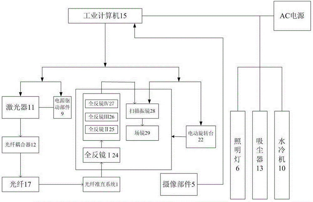
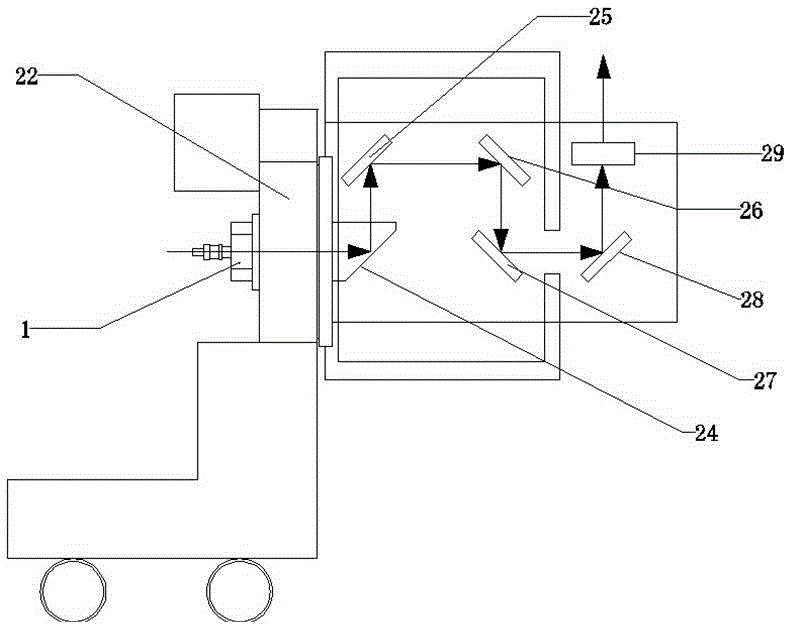
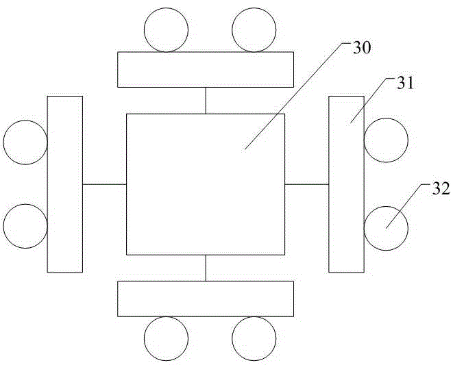
[0052] figure 1 It is a structural block diagram of a robot that adopts a laser to clean metal pipelines in the present invention. figure 2 It is a structural schematic diagram of the laser output part in the present invention, and the arrow in the figure indicates the direction of the optical path of the laser. image 3 It is a structural block diagram of the dust suction mechanism in the present invention. exist Figure 1-Figure 3 Among them, the robot using laser to clean metal pipes of the present invention includes a wheeled trolley, connecting parts, and a cabinet. Wherein, the wheeled trolley is provided with a laser output component, an imaging component 5, and a dust suction mechanism.

[0053] The laser output component includes an optical fiber collimation system 1 and a rotation auxiliary component; an electric rotation table 22, an electric translation table, and a total reflection mirror I24 are arranged on the rotation auxiliary component. The electric tra...


PUM


Abstract

The invention provides a robot for cleaning a metal pipeline by laser light. The robot comprises a wheel type trolley, a connecting component and an equipment cabinet. The wheel type trolley comprises a laser light output component, a camera shooting component and a dust collection mechanism. The connecting component comprises an optical fiber, a cable, a data line and a dust collection pipe. The equipment cabinet comprises a laser device, an optical fiber coupler, a power driving component, a water cooling machine, a dust collector and an industrial computer. Laser light is output by the laser device, coupled into the optical fiber through the optical fiber coupler and transmitted to an optical fiber collimation system in the laser light output component loaded on the wheel type trolley through the optical fiber, and then passes through a scanning galvanometer and a rotary accessory component in the laser light output component, so that a linear light spot capable of rotating by 360 degrees is output. The linear light spot rotates by 360 degrees to scan the inner wall of the metal pipeline, and therefore the purpose of cleaning the pipeline is achieved. The robot is used for cleaning the metal pipeline on line, and therefore the cleanness of the metal pipeline is kept on line.

Description

technical field [0001] The invention belongs to the technical field of laser cleaning equipment, and in particular relates to a robot that uses laser to clean metal pipes. Background technique [0002] For some metal pipes, such as light transmission pipes in high-power laser devices, after a period of use, particles, rust and other pollutants will appear on the surface of the pipe wall. Once the pipeline is installed, it cannot be disassembled and cleaned, and it is difficult for cleaning personnel to enter the pipeline for online cleaning. Laser cleaning technology can effectively remove particles, rust and other pollutants on the metal surface. Compared with other cleaning technologies (ultrasonic cleaning, chemical cleaning, grinding, etc.), this technology is characterized by: (1) good cleaning effect; (2) non-destructive Minimal damage; (3) No other reagents are used, non-toxic and harmless, and no additional pollution; (4) Can be cleaned online; (5) Does not affect t...

Claims


Application Information

Patent Timeline
Patent Type & Authority Applications(China)
IPC IPC(8): B08B7/00B08B15/04B08B9/049
CPCB08B7/0042B08B9/049B08B15/04
Inventor 袁晓东叶亚云蒋一岚贾宝申吕海兵廖威张传超苏春洲陈静张丽娟王海军栾晓雨倪卫赵吉宾隋春平
Owner LASER FUSION RES CENT CHINA ACAD OF ENG PHYSICS
Learn More