A scr injection metering module and control method

A technology of injection module and control method, which is applied in the direction of electric control, exhaust gas treatment, mechanical equipment, etc. of exhaust gas treatment device, can solve problems such as affecting normal operation and cooling, difficulty in production and maintenance, and large size, etc.

Active Publication Date: 2017-12-08
无锡恒和环保科技有限公司
View PDF1 Cites 1 Cited by
  • Summary
  • Abstract
  • Description
  • Claims
  • Application Information

AI Technical Summary

Problems solved by technology

Due to the high surface tension of the DEF working fluid, when filling the DEF working fluid, the liquid often cannot pass through the filter smoothly into the SCR metering pump, resulting in the difficulty of initial liquid intake
In addition, the SCR metering pump will generate a large amount of steam when it is working. If it cannot be removed in time, it will affect its normal work and cooling.
[0008] In addition, existing technology is difficult to work in any climate without auxiliary heating at all
Since the existing device for providing the jet power source is too large or cannot be implanted into the DEF liquid storage tank due to other reasons, an auxiliary ice-melting device is required, which makes the system more complex and bulky, and the cost remains high
Therefore, solving the problem of complex system structure is a realistic and urgent problem.
[0009] To sum up, the existing technology uses quite complex auxiliary devices to solve the problems of ice melting, cooling and crystallization prevention of the SCR injection metering device, which leads to new problems such as high manufacturing and use costs and difficult production and maintenance.

Method used


Image

  • A scr injection metering module and control method
  • A scr injection metering module and control method
  • A scr injection metering module and control method

Examples


Embodiment Construction

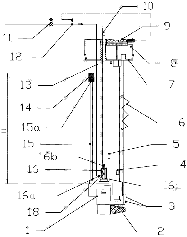
[0075] Such as figure 1 As shown, the structure diagram of the first embodiment of the SCR metering injection module provided by the present invention includes a pulse pump 1, a bracket 7, a nozzle 18, a gas-liquid mixing chamber 16, a controller 9, an upper end cover 8, a delivery pipe 10, and a filter Pressure regulating valve 11, compressed air control solenoid valve 12, compressed air pipe 13. The pulse pump 1 and the upper end cover 8 are installed on the two ends of the bracket 7 respectively, and the pulse pump 1 is fixedly connected with the bracket 7 as a whole through the screw thread 3 at the lowermost end of the bracket 7 . Upper end cover 8 is fixed on the upper end of support 7, and both can be a whole. The support 7 is also equipped with an electrically heated ice melter 6 , a liquid level sensor 4 and a temperature sensor 5 . The controller 9 is installed on the upper end cover 8, and the electrical connection lines on the bracket 7, including pulse pump driv...


PUM


Abstract

An SCR injection metering module and a control method therefor. The module comprises a bracket (7), a pulse pump (1) mounted at one end of the bracket (7), an upper end cover (8) fixed at the other end of the bracket (7), a spray nozzle (18) and a controller (9). The bracket (7) extends from the upper part of a DEF storage tank to the bottom of the DEF storage tank, and is fixed onto the storage tank through the upper end cover (8). The controller (9) controls the operation of the pulse pump (1). The pulse pump (1) comprises a solenoid driver (23) and a plunger pump (22), and an axially penetrating internal flow passage (21), wherein a DEF enters an inlet of the internal flow passage (21) through a first filter (2) arranged at the lower-end inlet of the internal flow passage (21), an outlet of the internal flow passage (21) is higher than the inlet of the internal flow passage (21), a part of the working fluid entering the internal flow passage (21) is pumped to the spray nozzle (18) by the plunger pump (22), and a part thereof is discharged to the pulse pump (1) from the outlet of the internal flow passage (21). The characteristic parameters of the pulse pump (1) are pre-stored in the controller (9), so that the controller (9) can operate in a passive mode or an intelligent mode.

Description

technical field [0001] The invention belongs to the technical field of engine exhaust aftertreatment, and in particular relates to a NOx selective catalytic reduction (SCR) system and its control technology for engine exhaust aftertreatment. Background technique [0002] With the increasingly prominent environmental problems, energy saving and emission reduction has become a hot topic at present, and the country has successively issued a series of vehicle emission standards. In this regard, vehicles powered by internal combustion engines need to be installed with exhaust after-treatment systems to meet the increasingly more stringent emission requirements. For example, SCR (Selective Catalytic Reduction) technology, which is currently mainly used for catalytic treatment of NOx and other pollutants in diesel engine exhaust. [0003] SCR technology needs to quantitatively inject 32.5% urea aqueous solution (also called diesel exhaust treatment fluid DEF=Diesel Exhaust Fluid, ...

Claims


Application Information

Patent Timeline
Patent Type & Authority Patents(China)
IPC IPC(8): F01N3/20F01N9/00
CPCF01N3/208F01N2610/02F01N2610/1406F01N2610/1426F01N2610/1433F01N2900/1812Y02T10/12
Inventor 郗大光杨延相张平
Owner 无锡恒和环保科技有限公司
Why Eureka
Try Eureka