Variable axial plunger pump

A technology for axial piston pumps and plunger pumps, which is applied in the direction of pumps, multi-cylinder pumps, liquid displacement machines, etc., and can solve the problems of expensive axial piston pump accessories, single variable control form, and difficult variable control. , to achieve the effect of compact structure, small volume and high speed

A technology for axial piston pumps and plunger pumps, which is applied in the direction of pumps, multi-cylinder pumps, liquid displacement machines, etc., and can solve the problems of expensive axial piston pump accessories, single variable control form, and difficult variable control. , to achieve the effect of compact structure, small volume and high speed

CN104948408AActive Publication Date: 2015-09-30湖南润田水工科技有限公司

Image

  • Variable axial plunger pump
  • Variable axial plunger pump
  • Variable axial plunger pump

Examples


Embodiment Construction

[0036] The embodiments of the present invention will be described in detail below with reference to the accompanying drawings, but the present invention can be implemented in various ways defined and covered by the claims.

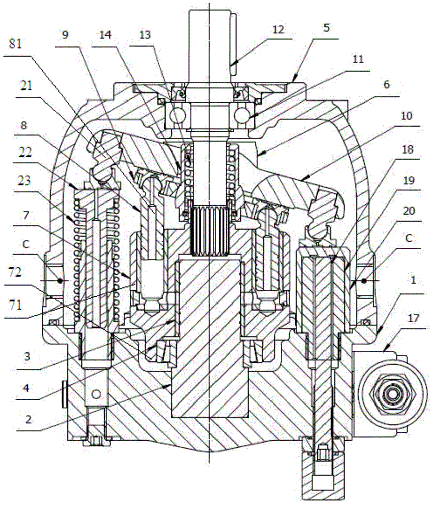
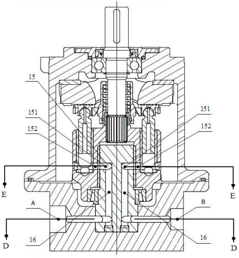
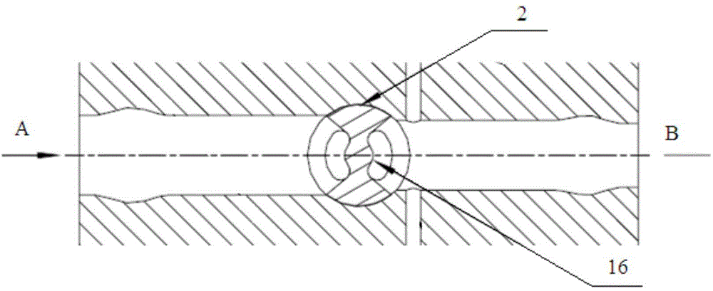
[0037] The present invention provides a variable variable axial plunger pump, the plunger pump is a radial flow distribution pump, including a drive shaft 12 driven to rotate by external force, a cylinder 7 connected to the drive shaft, a flow distribution sleeve 3, and a flow distribution shaft 2 And a variable control component that enables the plunger pump to output fluid in a variable manner; the cylinder body, the flow distribution sleeve and the flow distribution shaft are all arranged coaxially with the transmission shaft; the flow distribution sleeve is cylindrical, and the flow distribution sleeve is tightly connected to the cylinder In the cylindrical concave hole in the body; the rotation of the transmission shaft drives the cylinder body and the...


PUM


Abstract

The invention provides a variable axial plunger pump. The variable axial plunger pump is a radial fluid distribution pump and comprises a drive shaft driven to rotate by an external force, a cylinder body connected with the drive shaft, a fluid distribution sleeve, a fluid distribution shaft and a variable control part enabling the plunger pump to variably output a fluid. The cylinder body, the fluid distribution sleeve and the fluid distribution shaft are coaxial with the drive shaft. Compared with a traditional radial plunger pump, the variable axial plunger pump mainly has the advantages of being simple in structure, small in size and light in weight. Compared with a traditional axial plunger pump, the variable axial plunger pump mainly has the advantages that the rotation speed of the pump can be remarkably improved, working pressure can be remarkably increased, nominal flow rate can be improved in a multiplied mode, or the volume efficiency of the pump can be remarkably improved under the condition of the same working pressure, and noise can be reduced by more than 10 decibels.

Description

technical field [0001] The invention relates to the field of plunger pumps, in particular to a variable variable axial plunger pump. Background technique [0002] The plunger pump is a pump that relies on the reciprocating movement of the plunger in the cylinder to change the space volume of the sealed cavity to achieve oil suction or oil discharge. In the prior art, there are mainly two types of multi-piston piston pumps, one is an axial piston pump, and the other is a radial piston pump. [0003] Among them, the radial plunger pump means that the plungers are radially arranged and installed in the rotor, and the rotor and the plungers are driven to rotate by the motor. The plunger is pressed against the inner wall of the stator by the centrifugal force and the oil supplied by the low-pressure high-flow gear pump. Its structure is as Figure 4 Shown, wherein, 01, plunger, 02, rotor, 03, bushing, 04, stator, 05, oil distribution shaft. When the rotor rotates clockwise to ...

Claims


Application Information

Patent Timeline
30 Sep 2015
Publication
CN104948408A
IPC
F04B1/22; F04B1/30
Inventors
张意