Method for improving coaxial-cavity dielectric oscillator

A dielectric oscillator and coaxial cavity technology, applied in the direction of frequency selection two-terminal pair network, multi-terminal pair network, etc., can solve problems such as debugging difficulties

Inactive Publication Date: 2015-09-30
HUADONG PHOTOELECTRIC TECHN INST OF ANHUI PROVINCE
View PDF2 Cites 2 Cited by
  • Summary
  • Abstract
  • Description
  • Claims
  • Application Information

AI Technical Summary

Problems solved by technology

But for the 14.5GHz oscillator, it is difficult to use a quarter-wavelength mode resonator

Method used


Image

  • Method for improving coaxial-cavity dielectric oscillator

Examples


Embodiment Construction

[0015] For a quarter-wavelength mode coaxial cavity dielectric oscillator, a resonator with a dielectric constant of 21, the relationship between the length and the resonant frequency is as follows:

[0016] L=16.37 / F (1)

[0017] Wherein, L is the length of the coaxial cavity dielectric resonator in mm, and F is the resonant frequency of the coaxial cavity dielectric resonator in GHz. For a 14.5GHz oscillator, it is difficult to use a quarter-wavelength mode resonator to start oscillation directly at the desired frequency.

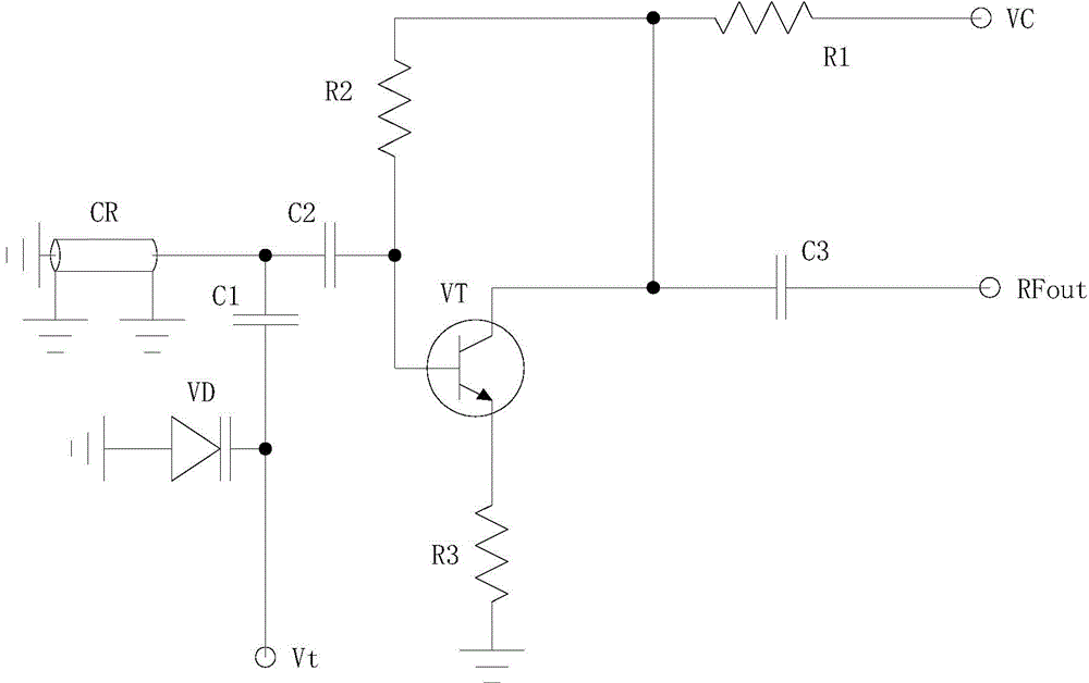
[0018] so if figure 1 As shown, the present invention reduces the output frequency of the oscillator, so that the coaxial cavity dielectric resonator works in the three-quarter wavelength mode. And make the coaxial cavity dielectric oscillator work in the Ku band, the present invention provides a method with strong operability and practicability, which weakens the disadvantage that the coaxial cavity dielectric resonator operating frequency is lower tha...


PUM

PropertyMeasurementUnit
Lengthaaaaaaaaaa

Abstract

The invention discloses a method for improving a coaxial-cavity dielectric oscillator. The method is characterized by comprising the following steps: reducing the output frequency of the coaxial-cavity dielectric oscillator to the half in a normal state; accessing the reduced output frequency to a high-pass filter and selecting second harmonics of the reduced output frequency; increasing the length of a resonator by three times than a quarter wavelength mode. The method has the advantages that the adjustment is more convenient and the operability is higher; the frequency variation is small, so that the difficulty in circuit debugging is greatly reduced.

Description

technical field [0001] The invention relates to a coaxial cavity dielectric oscillator, in particular to an improved method of the coaxial cavity dielectric oscillator. Background technique [0002] Microwave oscillator is one of the important components widely used in various microwave systems such as communication, radar, electronic countermeasures and test instruments, and its performance will directly affect the quality of the microwave system and measurement accuracy. [0003] According to the shape and structure of the resonator used, the microwave dielectric oscillator can be divided into a coaxial cavity dielectric oscillator and a cylindrical dielectric oscillator. The cylindrical dielectric resonator is bonded on the circuit board with glue, and there is a risk of glue aging and failure over time. Different from the cylindrical dielectric resonator, the coaxial cavity dielectric resonator is directly welded on the circuit board, so the installation is reliable and...

Claims


Application Information

Patent Timeline
IPC IPC(8): H03H11/04
Inventor 刘劲松王华曲燕霞
Owner HUADONG PHOTOELECTRIC TECHN INST OF ANHUI PROVINCE
Why Eureka
Try Eureka