A left auricle occluding device

A technology of occluder and sealing disc, which is applied in the field of medical devices, can solve problems such as stress concentration, increased risk of thrombus, and surgical failure, and achieve the effect of eliminating local stress concentration, reducing the risk of puncture, and achieving repeatable release

Active Publication Date: 2015-10-07
HANGZHOU NUOMAO MEDTECH CO LTD
View PDF5 Cites 34 Cited by
  • Summary
  • Abstract
  • Description
  • Claims
  • Application Information

AI Technical Summary

Problems solved by technology

If the occlusion disk cannot fit in the opening of the LAA after release, and the anchor disk cannot be retracted into the sheath, it will lead to surgical failure and may further increase the risk of thrombosis, so the anchor disk can be released repeatedly. Very important
[0011] In the prior art, there are also anchoring discs that can achieve repeated release, but the entire anchoring disc is not fixed inside the left atrial appendage with uniform force, but is fixed through several local areas, which will cause these several The stress concentration in the area, and the barbs in these areas will also have the risk of piercing the wall of the left atrial appendage, leading to complications such as pericardial effusion

Method used


Image

  • A left auricle occluding device
  • A left auricle occluding device
  • A left auricle occluding device

Examples


Embodiment 1

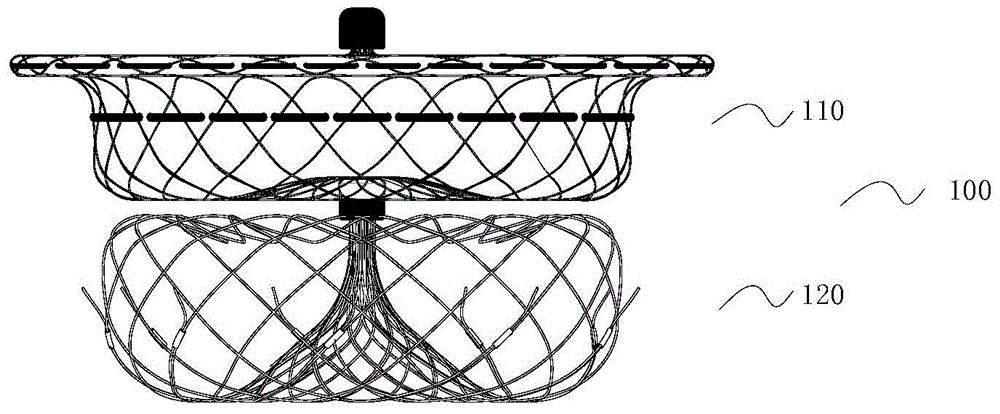
[0096] Such as figure 1 As shown, the left atrial appendage occluder 100 provided by the present invention is composed of a sealing disc 110 and an anchoring device 120 .

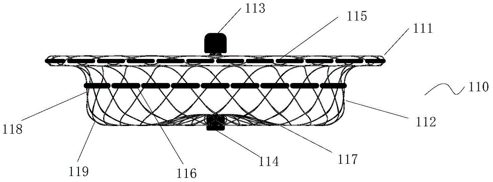
[0097] The sealing disc 110 is a mesh structure braided by nickel-titanium wire, such as figure 2 As shown, the sealing disc 110 is composed of a disc surface 111 and a waist 112, a first fixed end 113 is provided at the center of the disc surface, a second fixed end 114 is provided at the center of the waist 112, and a layer of PET flow blocking film 115 is sewn inside the disc surface. A layer of flow blocking film 116 is sewn inside the waist portion 112 .

[0098] The first fixed end 113 is used to connect with the delivery device, and the second fixed end 114 is connected with the anchoring device 120 .

[0099] Such as figure 2 As shown, the waist 112 includes a diffusion section 117 radiating outward from the second fixed end 114, and a cylindrical body section 118 on the periphery of the diffus...

Embodiment 2

[0121] The difference between this embodiment and Embodiment 1 is that each nickel-titanium wire 2221 used to form the barb is connected to one of the inverted V-shaped nickel-titanium wires 2222 in the anchoring mesh frame by welding, and the welding area The length of 2223 is 2 mm, and the welding area 2223 is close to the apex 2224 where the two sides of the inverted V-shaped nickel-titanium wire intersect. The end 2225 of the nickel-titanium wire 2221 extending out of the welding area 2223 forms a barb 227, and the length of the end 2225 is 2 mm ( Figure 11b In H2=2mm), the distance between the end point 2226 of the end portion 2225 and the apex 2224 of the inverted V-shaped nickel-titanium wire is 8mm, as Figure 11a , Figure 11b , Figure 12a , Figure 12b shown.

Embodiment 3

[0123] The difference between this embodiment and Embodiment 1 is that the total length of each nickel-titanium wire 3221 used to form the barb is 5 mm, and the nickel-titanium wire 3221 is divided into a fixed section and a free section, and the fixed section passes through the steel sleeve 3223 and the free section. The nickel-titanium wire 3222 of the anchoring device frame is connected together, the length of the fixed section is 3mm, and the fixed section is completely located inside the steel sleeve 3223; 2mm (ie Figure 13b In H3=2mm), the distance between the end point 3226 of the free section 3225 and the apex 3224 of the inverted V-shaped nickel-titanium wire is 8mm, as Figure 13a , Figure 13b , Figure 14a , Figure 14b shown.


PUM


Abstract

The invention discloses a left auricle occluding device. The left auricle occluding device comprises a sealing disc and an anchoring device, both of which are connected. The position where the anchoring device is matched with a left auricle is an anchoring net of a boneless structure. The overall anchoring device is of a boneless structure and formed by weaving of hyper-elastic metal wires or memory alloy metal wires. The far end of the anchoring device is in the shape of an opening. The near end of the anchoring device is collected and connected with the sealing disc to form a conical net. The far end of the anchoring device is opened and turned up towards the near end to form the anchoring net surrounding the conical net. The anchoring net is joined with the conical net by means of a circular transition area. The left auricle occluding device has following beneficial effects: force can be uniformly distributed to be anchored in the interior of the left auricle in order to eliminate concentration of local stress and can also be repeatedly released; and an opening part of the left auricle is effectively and reliably blocked.

Description

technical field [0001] The invention relates to the technical field of medical instruments, in particular to a left atrial appendage occluder. Background technique [0002] Atrial fibrillation (abbreviated as atrial fibrillation) is the most common sustained arrhythmia, and with age, the incidence of atrial fibrillation continues to increase, reaching 10% in people over 75 years old. [0003] During atrial fibrillation, the frequency of atrial excitation reaches 300-600 beats per minute, the heartbeat frequency is often fast and irregular, and the atrium loses effective systolic function. In atrial fibrillation, the contractility of the left atrial appendage decreases, coupled with the morphological characteristics of the left atrial appendage itself and the unevenness of the muscle trabeculae in the left atrial appendage, the blood flow in the left atrial appendage produces vortices and slows down the flow rate, which promotes the formation of thrombus. In patients with no...

Claims


Application Information

Patent Timeline
Patent Type & Authority Applications(China)
IPC IPC(8): A61B17/12
CPCA61B17/12022A61B17/12031A61B17/12122A61B17/1214A61B2017/00238A61B17/12172A61B17/12177A61B2017/00867A61B2017/00526A61B17/12A61B17/12145
Inventor 王永胜张庭超訾振军
Owner HANGZHOU NUOMAO MEDTECH CO LTD
Why Eureka
Try Eureka