Externally-cooled electronic condenser

A technology of condenser and electronic refrigeration, which is applied in the direction of laboratory equipment, heating or cooling equipment, chemical instruments and methods, etc., can solve the problem that the cooling effect of electronic condenser is not effectively exerted, the structure of internal condensation electronic condenser is complex, It is not easy to manufacture and process problems, and achieve the effect of simple structure, easy popularization and easy processing and manufacturing

Inactive Publication Date: 2015-10-07
李景峰 +1
View PDF5 Cites 1 Cited by
  • Summary
  • Abstract
  • Description
  • Claims
  • Application Information

AI Technical Summary

Problems solved by technology

CN 101862689B invention patent discloses an experimental device for direct cooling electronic condenser without cooling water. The electronic condenser has no pollution, no noise, no cooling medium, and can completely solve the problem of waste of tap water resources; it is cooled by electronic refrigeration elements. The end absorbs heat to reduce the temperature and transmits it to the cold collector inside the condenser tube space, reducing the condensation temperature in the system, which belongs to the internal cooling electronic condenser; however, the room temperature environment that the condenser tube is in contact with outside will also have an effect on the cooling inside the condenser tube. A certain offset effect, and the loss of cooling temperature will also be caused during the conduction process from the cold end of the electronic refrigeration element to the collector, so that the cooling effect of the electronic condenser has not been effectively exerted, and the structure of the internal condensation electronic condenser is relatively Complex, not easy to manufacture and process

Method used


Image

  • Externally-cooled electronic condenser
  • Externally-cooled electronic condenser
  • Externally-cooled electronic condenser

Examples


Embodiment Construction

[0027] The present invention will be further described in detail below in conjunction with the drawings and specific embodiments:

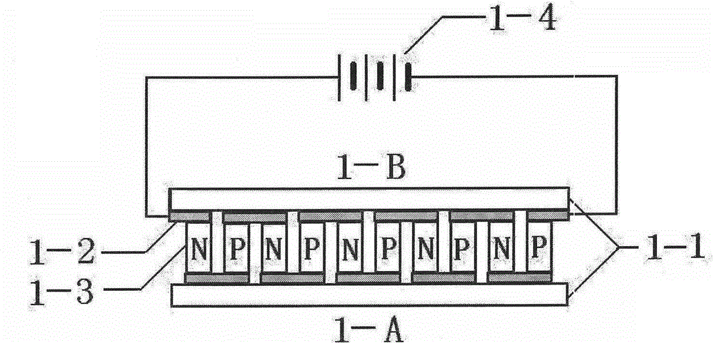
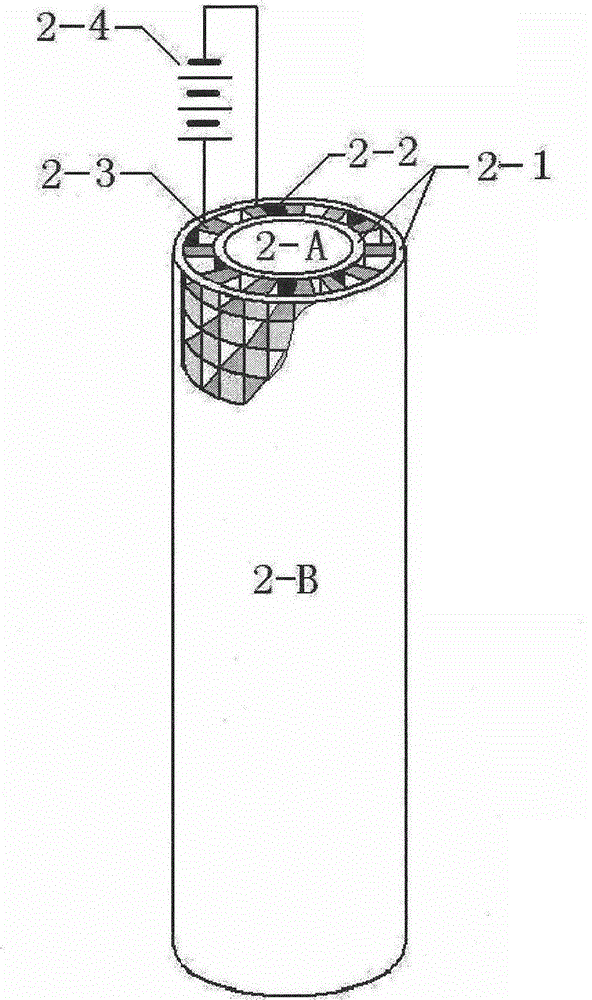
[0028] The structure and working principle of electronic refrigeration components such as figure 1 , figure 2 As shown, 1-1 and 2-1 are insulating ceramics, 1-2 and 2-2 are metal conductors, 1-3 and 2-3 are N-type and P-type semiconductors, and 1-4 and 2-4 are DC power supplies . After the DC power supply is connected to the electronic refrigeration component, energy transfer occurs immediately. The current flows from the N-type component to the P-type component to absorb heat, and the 1-A and 2-A surfaces become the cold end and the temperature decreases; the P-type component flows to the N The joint of the type element releases heat, and the 1-B and 2-B surfaces become the hot end and the temperature increases. Generally, the temperature difference between the hot and cold ends of electronic refrigeration components can reach between 40 and 65 de...


PUM


Abstract

The invention discloses an externally-cooled electronic condenser and solves the problem that the existing water-cooled condenser wastes a great deal of tap water. The outside of a condensing tube is isolated from the ambient heat, and the larger cooling area leads to evident increase in distillation or reflux condensing efficiency. The externally-cooled electronic condenser comprises a tubular electronic refrigerating element, a tubular air radiator and a finned condensing tube. During operating, the cold end of the tubular electronic refrigerating element sucks interior heat of the finned condensing tube to lower the temperature, the distilled or reflux steam is condensed, the hot end of the tubular electronic refrigerating element releases the heat which is guided out by air from the tubular air radiator, and low condensing temperature is continuously kept for the cold end; according to the condensing temperature of fraction, by adjusting input current of the externally-cooled electronic condenser, the condensing temperature can be under high-precision control; the existing distillation or reflux test water-cooled condensation is replaced; the externally-cooled electronic condenser is simple in structure, easy to manufacture, easy to popularize and significant to the building of water-saving society.

Description

Technical field [0001] The invention relates to scientific research institutes, colleges and universities, and enterprise R&D institutions in the chemical, chemical, pharmaceutical, food, environmental and other industries; specifically belongs to the field of experimental instrument and equipment technology manufacturing, and particularly relates to an external cooling type that replaces water-cooled condensers. Electronic condenser. Background technique [0002] For a long time, the whole society has been vigorously advocating water conservation. In industry, agriculture, service industry, daily life and other aspects of water conservation facilities, active and effective water conservation methods and measures have been adopted, and obvious results have been achieved. However, research institutes, school laboratories, and other research and educational institutions, or research departments engaged in water-saving research on their own, have turned a deaf ear to the waste of ex...

Claims


Application Information

Patent Timeline
IPC IPC(8): B01L7/00
Inventor 李景峰
Owner 李景峰
Why Eureka
Try Eureka