Combined circulating energy supplying system

A combined cycle and energy supply technology, applied in the direction of fluid circulation arrangement, irreversible cycle compressor, heating and refrigeration combination, etc.

Active Publication Date: 2015-10-07
李华玉
View PDF5 Cites 16 Cited by
  • Summary
  • Abstract
  • Description
  • Claims
  • Application Information

AI Technical Summary

Problems solved by technology

[0002] In the system where fuel is used for heating by combustion, there is a large temperature difference between the gas formed by combustion and the heated medium; There is also a large temperature difference; in distributed energy systems that use fuel combustion to provide heat sources, power supply is actually a restrictive additional condition, and there are still situations where the temperature difference cannot be fully utilized in many cases
Summarize the situation that it is difficult to realize the efficient utilization of heat energy, which can be mainly summarized into six aspects: ①Under the condition of no power load, there is a large temperature difference between the gas and the heated medium that cannot be used, and the efficient utilization of heat energy cannot be realized; ②Absorption heat pump is configured , due to the limitation of the worki

Method used


Image

  • Combined circulating energy supplying system
  • Combined circulating energy supplying system
  • Combined circulating energy supplying system

Examples


Embodiment Construction

[0091] The first thing to explain is that in the expression of the structure and process, it will not be repeated if it is not necessary; the obvious process will not be expressed. The present invention will be described in detail below in conjunction with the accompanying drawings and examples.

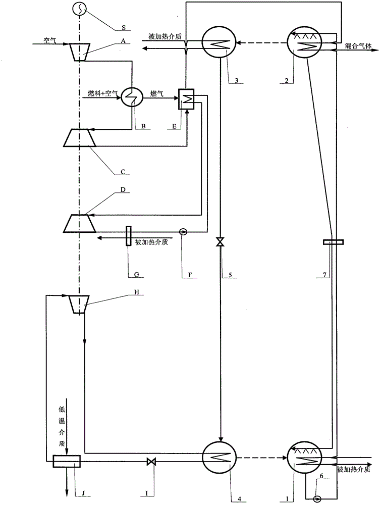
[0092] figure 1 The combined cycle energy supply system shown is realized as follows:

[0093] (1) Structurally, it mainly consists of compressor, boiler, air turbine, steam turbine, waste heat boiler, circulating pump, heat exchanger, compressor, low temperature throttle valve, low temperature heat exchanger, evaporator, absorber, generator It is composed of a condenser, a condenser, a throttle valve, a solution pump, a solution heat exchanger and a working machine; the compressor A has an air channel to communicate with the outside, and the compressor A has a compressed air channel to communicate with the boiler B, and then the boiler B has a compression The air passage communica...


PUM


Abstract

The invention provides a combined circulating energy supplying system, and belongs to the technical field of heat energy utilization and heat pumps. An air-steam forward circulating system is constituted by an air compressor, a boiler, an air turbine, a steam turbine, a waste heat boiler, a circulating pump and a heat exchanger, a compressed backward circulating system is constituted by a compressor , a second condenser, an evaporator, a low-temperature throttling valve, a second low-temperature throttling valve and a low-temperature heat exchanger, and an absorption type backward circulating system is constituted by an absorber, a generator, a condenser, the evaporator, a throttling valve, a solution pump and a solution heat exchanger; the air-steam forward circulating system provides power for the compressed backward circulating system and provides driving heat load for the absorption type backward circulating system, the compressed backward circulating system obtains low temperature heat load and respectively provides heat for the outside through the second condenser and the absorption type backward circulating system through the evaporator, and the absorption type backward circulating system provides the heat for the outside through the absorber and the condenser, so that the combined circulating energy supplying system is formed.

Description

Technical field: [0001] The invention belongs to the technical field of power, refrigeration and heat pump. Background technique: [0002] In the system where fuel is used for heating by combustion, there is a large temperature difference between the gas formed by combustion and the heated medium; There is also a large temperature difference; in distributed energy systems that use fuel combustion to provide heat sources, power supply is actually a restrictive additional condition, and there are still situations where the temperature difference cannot be fully utilized in many cases. Summarize the situation that it is difficult to realize the efficient utilization of heat energy, which can be mainly summarized into six aspects: ①Under the condition of no power load, there is a large temperature difference between the gas and the heated medium that cannot be used, and the efficient utilization of heat energy cannot be realized; ②Absorption heat pump is configured , due to the...

Claims


Application Information

Patent Timeline
IPC IPC(8): F01K11/02F01K17/02F25B25/02F25B1/10F25B41/06F25B29/00F25B41/31
Inventor 李华玉
Owner 李华玉
Why Eureka
Try Eureka