Composite heat exchange type moving heat supply device

A heat-supply device and heat-exchange technology, applied in the field of composite heat-exchange mobile heat-supply devices, can solve the problems of reduced heating efficiency, long charging time, and increased circulation resistance of fluid working fluid, etc., to achieve increased circulation flow, high The heat storage density and the effect of increasing the direct contact heat transfer area

Inactive Publication Date:
View PDF10 Cites 6 Cited by
  • Summary
  • Abstract
  • Description
  • Claims
  • Application Information

AI Technical Summary

Problems solved by technology

During the heat charging (heat storage) process, the nozzle sprays high-temperature fluid working medium into the natural pores of the solid phase change heat storage material, gradually melting the phase change heat storage material, forming a flow microchannel inside to expand the contact area and realize Heat charging cycle, but there are some obvious technical deficiencies in this, including: (1) The fluid working medium ejected from the nozzle cannot quickly break through a large amount of solid phase change heat storage material to form a large flow heat charging cycle, and the expansion speed of the heat exchange contact area (2) The fluid working medium nozzle has no shielding mechanism, and the deposited phase change heat storage material is easy to block the inlet pipeline at the bottom, which increases the circulation resistance of the fluid working medium, resulting in a significant decrease in heating efficiency; ( 3) The mobile heating device has no monitoring equipment for temperature, pressure, flow and other parameters, and has no ability to automatically adjust thermal parameters

Method used


Image

  • Composite heat exchange type moving heat supply device
  • Composite heat exchange type moving heat supply device
  • Composite heat exchange type moving heat supply device

Examples


Embodiment Construction

[0029] The present invention will be further described below in conjunction with the accompanying drawings and specific embodiments.

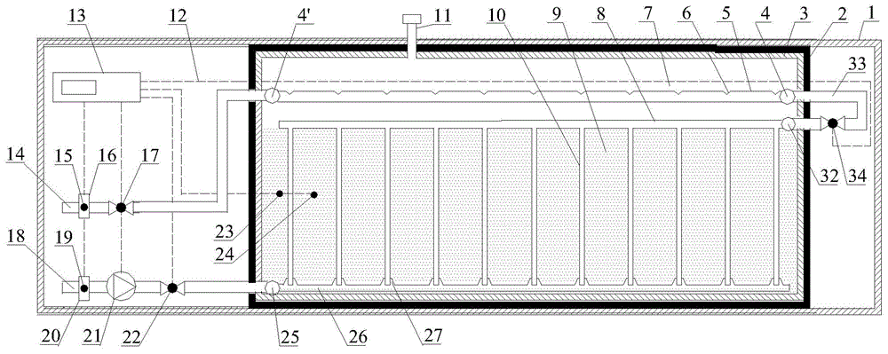
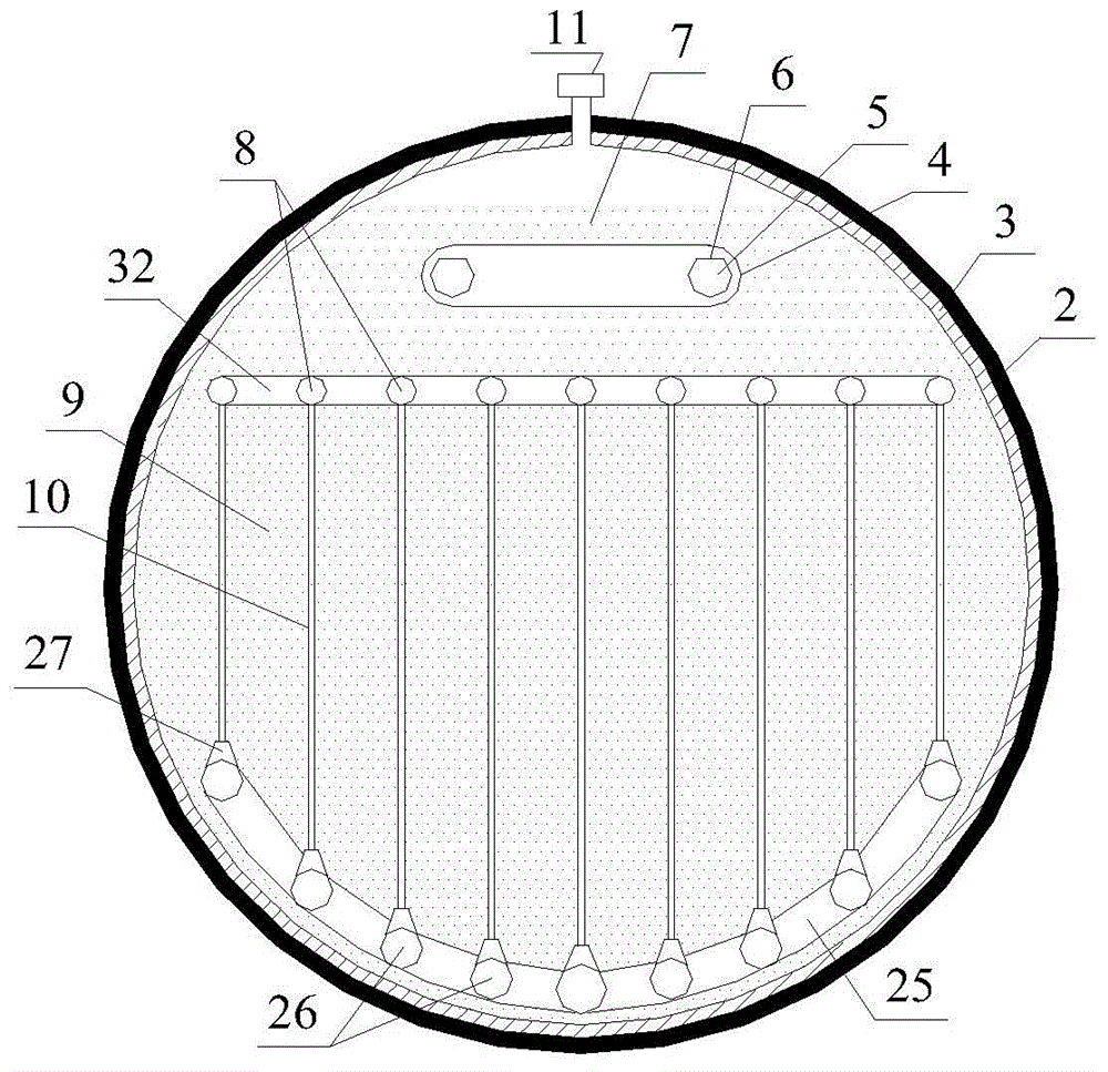
[0030] Such as figure 1 , figure 2As shown, the compound heat exchange type mobile heating device of the present invention includes an outer box body 1 and a heat storage tank 3 located in the outer box body 1, and the inlet dry pipe 18, the outlet dry pipe 14, and the external dry pipe drawn from the heat storage tank 3 33, and the automatic monitor 13 located in the outer casing 1. One end of the inlet dry pipe 18 and the outlet dry pipe 14 drawn from the heat storage tank is connected to the heat exchanger at the heat source end or the heat exchanger at the user end, the other end of the inlet dry pipe 18 is connected to the downlink pipe 25 in the heat storage tank, and the outlet dry pipe The other end of 14 is connected with the second porous pipe union 4 in the heat storage tank; one end of the external dry pipe 33 drawn from the heat...


PUM


Abstract

The invention discloses a composite heat exchange type moving heat supply device which comprises an outer box, a heat storage tank located in the outer box, an inlet main pipe, an outlet main pipe, an external main pipe and an automatic controller. The inlet main pipe, the outlet main pipe and the external main pipe are led from the heat storage tank, and the automatic controller is located in the outer box. A heat exchange pipe is vertically buried in a phase-change heat storage material in the heat storage tank. The upper end of the heat exchange pipe is perpendicularly connected with an inlet branch pipe, and the lower end of the heat exchange pipe is inserted in a nozzle of the inlet branch pipe. The nozzle is sealed through a nozzle cap under the elasticity of a spring. A porous pipe is arranged in a fluid working medium in the heat storage tank. During heat charging, the high-temperature fluid working medium enters the heat exchange pipe to conduct indirect contact heat exchange circulation with the phase-change heat storage material, a fluid channel is formed in the solid phase-change heat storage material, and then the fluid working medium is controlled to be sprayed into the fluid channel from the nozzle to conduct direct contact heat exchange circulation with the phase-change heat storage material. During heat supply, an automatic controller adjusts the flow of direct contact heat exchange circulation by monitoring a sensor and controlling the opening degree of an electric valve, and therefore the heat supply temperature is controlled.

Description

technical field [0001] The invention relates to a compound heat exchange type mobile heat supply device. Background technique [0002] Mobile heating technology is an emerging method, that is, industrial waste heat and waste heat recovery are stored in mobile heating devices, and then transported to users by means of transportation to release the stored heat for their use. Mobile heating breaks the mode of relying on pipelines to transport heat. It can economically and flexibly collect and store waste heat with scattered locations and discontinuous time, and supply heat to scattered users in the form of distribution. It solves the gap between the output and utilization of waste heat resources. There is a time and regional mismatch problem, which greatly improves the comprehensive utilization rate of energy, reduces the user's use cost, and reduces harmful gas emissions. [0003] At present, equipment or devices for mobile heating based on phase change heat storage technolog...

Claims


Application Information

Patent Timeline
Patent Type & Authority Applications(China)
IPC IPC(8): F24D15/02F24D19/10
Inventor 朱晓林王志峰杨铭邓杰
Why Eureka
Try Eureka