
Optical fiber connector and manufacturing method thereof

A technology for optical fiber connectors and optical fiber ferrules, which is applied in the field of manufacturing optical fiber connectors and optical fiber connectors. It can solve the problems of no structure, scratches on the surface, and affecting the performance of optical fiber connectors. Cooperate with the requirements of precision and improve the effect of anti-interference ability

Active Publication Date: 2015-10-07
SHENZHEN EPLU SCI TECH
View PDF11 Cites 13 Cited by
  • Summary
  • Abstract
  • Description
  • Claims
  • Application Information

AI Technical Summary

Problems solved by technology

Its disadvantage is that the end face of the ferrule is usually not protected by a structure, which easily causes the surface to be scratched, thereby affecting the performance of the optical fiber connector

Method used


Image

  • Optical fiber connector and manufacturing method thereof
  • Optical fiber connector and manufacturing method thereof
  • Optical fiber connector and manufacturing method thereof

Examples


Embodiment Construction

[0029] The present invention will be described in further detail below in conjunction with accompanying drawing:

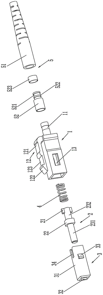
[0030] see figure 1 As shown, the optical fiber connector includes a housing 1 and an optical fiber ferrule 2 disposed in the housing 1, the end face of the optical fiber ferrule 2 is provided with at least one lens (not shown in the figure), and the housing 1 A ferrule protection structure 3 is installed in the cavity at one end to protect the end face of the ferrule to prevent the mirror surface of the ferrule end face from being damaged or scratched. 231 to ensure the free expansion and contraction of the ferrule protection structure 3. The other end of the housing 1 is provided with an extension tube 11. The extension tube 11 is connected to protect the optical cable from bending and ensure the normal transmission of the optical fiber connector under bending stress. The tail sheath assembly 5 of the optical signal, the outer wall of the housing 1 is integrall...


PUM


Abstract

The invention relates to an optical fiber connector and a manufacturing method thereof. The optical fiber connector comprises a housing and a fiber insertion core arranged in the housing. The end surface of the fiber insertion core is provided with at least one lens. The cavity at one end of the housing is equipped with an insertion core protection structure for protecting the end surface of the insertion core so as to prevent the lens surface at the end surface of the fiber insertion core from being damaged or scraped. The insertion core protection structure is internally provided with the fiber insertion core and an elastic component sleeved on a fiber insertion core tubular body to ensure free telescoping of the insertion core protection structure. The other end of the housing is provided with an extension pipe. The extension pipe is connected with a tail sheath assembly which carries out bending protecting on an optical cable and guarantees that the optical fiber connector can transmit optical signals normally under the bending pressure condition. An elastic buckle structure for enabling the optical fiber connector to be buckled to a corresponding insertion hole of an adapter is integrated to the outer wall of the housing.

Description

technical field [0001] The invention relates to an optical fiber connector, in particular to an optical fiber connector and a method for manufacturing the optical fiber connector. Background technique [0002] CN201320876799.1 discloses a fiber optic ferrule and a connector with the fiber optic ferrule. Its purpose is to provide a fiber optic ferrule and a connector with the fiber optic ferrule. The front end of the fiber optic ferrule is provided with a lens, The light spot of the optical fiber can be enlarged to enhance the coupling effect of the optical signal. The technical solution: the optical fiber ferrule includes a ferrule body, the ferrule body has an inner hole, and the inner hole at least includes a first hole section that is suitable for the diameter of the bare optical fiber, and the front end of the ferrule body is provided with a A lens for expanding the diameter of the light beam emitted from the bare optical fiber to the front end of the ferrule body or re...

Claims


Application Information

Patent Timeline
Patent Type & Authority Applications(China)
IPC IPC(8): G02B6/38
CPCG02B6/3825G02B6/3833G02B6/3849G02B6/3853G02B6/3874G02B6/3887
Inventor 钟志云周震王七月
Owner SHENZHEN EPLU SCI TECH
Learn More