Switch reluctance machine torque ripple control system and control method therefor

A switched reluctance motor and torque technology, used in control systems, vector control systems, motor generator control, etc. Effect

Inactive Publication Date: 2015-10-07
ZHEJIANG HUAFENG ELECTRIC TOOLS
View PDF2 Cites 15 Cited by
  • Summary
  • Abstract
  • Description
  • Claims
  • Application Information

AI Technical Summary

Problems solved by technology

Especially when the harmonic frequency of the radial magnetic force coincides with the defined natural frequency, the vibration and noise caused by resonance will be even worse

Method used


Image

  • Switch reluctance machine torque ripple control system and control method therefor
  • Switch reluctance machine torque ripple control system and control method therefor
  • Switch reluctance machine torque ripple control system and control method therefor

Examples


Embodiment 1

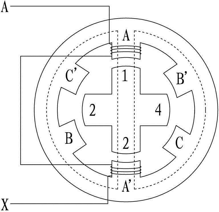
[0029] For switched reluctance motors, when the center of the salient pole of the stator coincides with the center of the groove of the rotor, the inductance is the smallest and the reluctance is the largest; the leading edge of the salient pole of the rotor is aligned with the trailing edge of the salient pole of the stator, and the alignment of the two begins to increase with the increase of the rotor angle As the overlap increases, the phase inductance begins to increase until the salient poles of the rotor and the salient poles of the stator overlap completely, at this time the inductance is the largest and the reluctance is the smallest.

[0030] In the case of ignoring the resistance voltage drop of the phase winding, the phase voltage equation is ±U=dψ / dt, where ±U is the terminal voltage of the winding when the power device is turned on; -U is the terminal voltage of the winding when the power device is turned off, Ψ is the winding flux linkage.

[0031] Assuming that ...


PUM


Abstract

The invention belongs to the field of motor control, specifically a switch reluctance machine torque ripple control system and a control method therefor. The system comprises a delay controller, a hysteresis controller, a PWM output control device, an SRM (switch reluctance machine), a current detection device, a multiplexer, and a rotor position estimation device. The delay controller is connected with the hysteresis controller, the hysteresis controller is connected with the PWM output control device, and the PWM output control device is connected with the SRM. The SRM is connected with the SRM is connected with the current detection device and the multiplexer, and the multiplexer is connected with the rotor position estimation device. The rotor position estimation device is connected with the delay controller. Through the control of a radial force between adjacent poles of the SRM, the system employs the principle of torque recombination to effectively inhibit the periodic disturbance of the SRM, and solves a problem of motor system vibration caused by the torque ripple of the SRM in operation.

Description

technical field [0001] The invention belongs to the field of motor control, and in particular relates to a switched reluctance motor torque ripple control system and a method for applying the system to waveform control and rotor position estimation. technical background [0002] Switched reluctance motor is a new type of speed regulation motor. The speed regulation system has the advantages of both DC and AC speed regulation systems. It is the latest generation of stepless speed regulation system following the frequency conversion speed regulation system and brushless DC motor speed regulation system. Due to its simple and solid structure, the switched reluctance motor has a wide speed regulation range, excellent speed regulation performance, high efficiency in the entire speed regulation range, and high system reliability. It is more suitable for power tools, household appliances, fitness equipment and other occasions. The double-saliency structure and switching power suppl...

Claims


Application Information

Patent Timeline
Patent Type & Authority Applications(China)
IPC IPC(8): H02P21/05
Inventor 辛永良陈艳庆
Owner ZHEJIANG HUAFENG ELECTRIC TOOLS
Why Eureka
Try Eureka