Check patentability & draft patents in minutes with Patsnap Eureka AI!

Sensor apparatus for determining at least one rotation property of a rotating element

A technology of sensor devices and rotating components, applied in the direction of converting sensor output, using electric/magnetic devices to transfer sensing components, measuring devices, etc., can solve the problem of speed sensor not providing accuracy, etc., and achieve the effect of improving signal-to-noise ratio

Inactive Publication Date: 2015-10-07
ROBERT BOSCH GMBH
View PDF6 Cites 10 Cited by
  • Summary
  • Abstract
  • Description
  • Claims
  • Application Information

AI Technical Summary

Problems solved by technology

However, the known rotational speed sensors do not provide the accuracy required according to the latest requirements over the entire rotational speed range in electric motors, generally from 1 to approximately 25.000 revolutions per minute, especially in the lower and upper marginal ranges

Method used


Image

  • Sensor apparatus for determining at least one rotation property of a rotating element
  • Sensor apparatus for determining at least one rotation property of a rotating element

Examples


Embodiment Construction

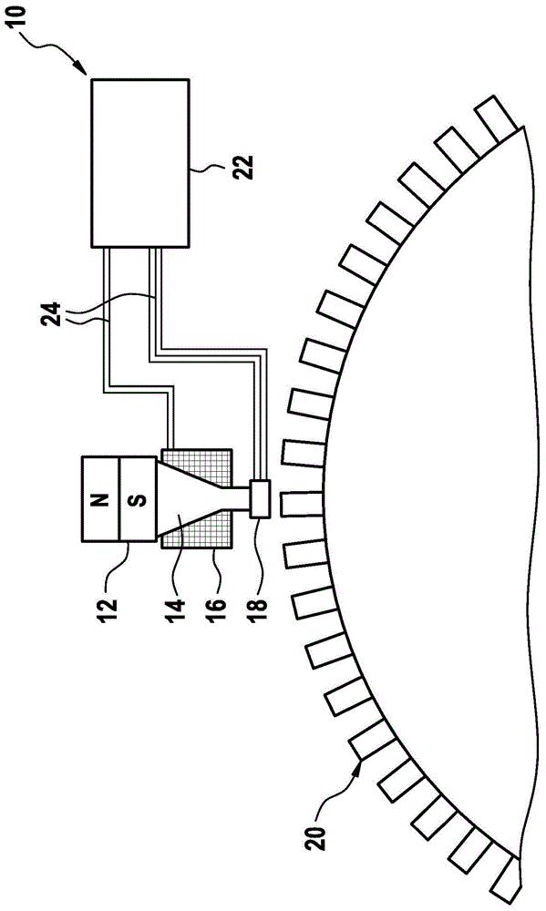
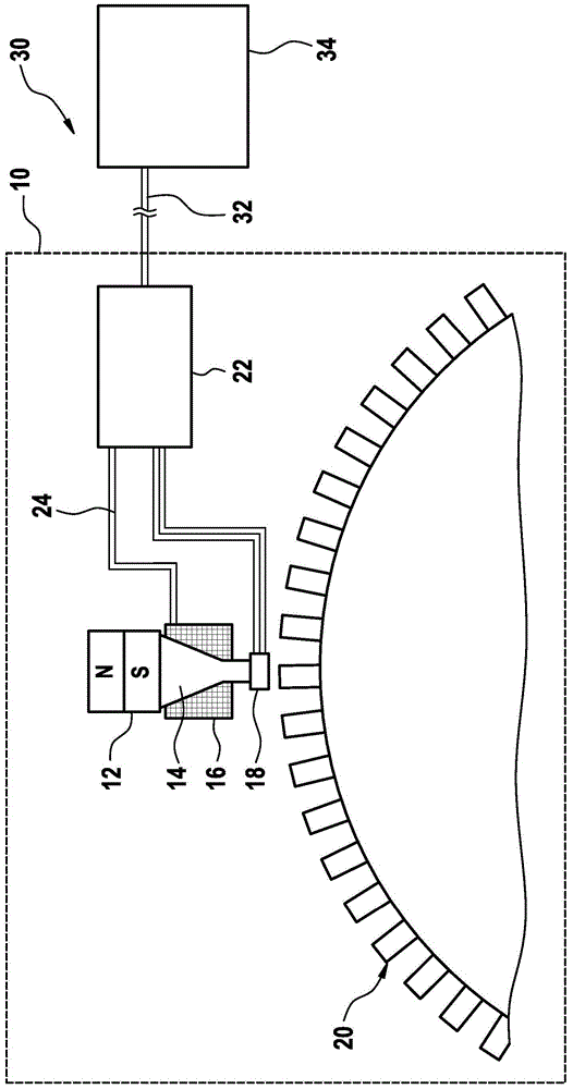
[0030] if available from figure 1 The illustrated embodiment of the sensor device 10 has a magnetic field generator 12, which can be formed, for example, by a permanent magnet. As shown, the sensor device 10 further comprises a flow guide element 14 which is arranged in the form of a surface on the south pole of the magnetic field generator 12 shown as a dipole magnet, which flow guide element is simultaneously directed in the direction of the rotating element (not shown). extend. Here, as an alternative, the magnetic field generator 12 can also be provided with a polarity orientation opposite to that of the components shown.

[0031] Furthermore, a first magnetic sensor 16 is arranged, preferably in the form of a coil 16 surrounding the flow guide element 14, and a second magnetic sensor 18 is arranged, preferably in the direction of the flow guide element 14 on the end face of the rotating element. Here, preferably, the second magnetic sensor 18 is not surrounded by the c...


PUM


Abstract

The invention proposes a sensor apparatus (10) for determining at least one rotation property of a rotating element, comprising at least one increment carrier (20) which can be connected to the rotating element, wherein the sensor apparatus (10) comprises at least one magnetic field generator (12) for generating a magnetic field at the location of the rotating element, wherein the sensor apparatus (10) has at least one first magnetic sensor (16) and at least one second magnetic sensor (18), wherein the first magnetic sensor (16) generates a first sensor signal and the second magnetic sensor (18) generates a second sensor signal, wherein the first magnetic sensor (16) is an inductive sensor, wherein the first magnetic sensor (16) has at least one coil and is set up to detect a magnetic field generated or changed by eddy currents of the rotating element, wherein the second magnetic sensor (18) is an active sensor, and wherein the second magnetic sensor (18) has at least one Hall element and / or at least one magnetoresistive element.

Description

Background technique [0001] Numerous sensors are known from the prior art, which sense at least one rotational characteristic of the rotating element. Here, a rotational characteristic is generally understood as a characteristic that at least partially accounts for the rotation of a rotating element. Here, for example, angular velocity, rotational speed, angular acceleration, rotational angle, angular position or other properties that can characterize a continuous or discontinuous, monotonic or variable rotation or rotation of the rotary element can be involved. Sensors of this type are described, for example, in Konrad Reif, Sensoren im Kraftfahrzeug (Sensors in Motor Vehicles), 1st Edition 2010, pages 63 to 73 and 120 to 129. A particular focus of the present invention is on rotational speed sensing, however in principle the invention is not limited to this. In particular, rotational speed sensing can be provided to sense the rotational speed of a crankshaft or a camshaft,...

Claims


Application Information

Patent Timeline
IPC IPC(8): G01D5/14G01D5/20
CPCG01D5/147G01D5/2013
Inventor J·施奈德A·亚山S·费勒J·文特
Owner ROBERT BOSCH GMBH
Features
  • R&D
  • Intellectual Property
  • Life Sciences
  • Materials
  • Tech Scout
  • Unparalleled Data Quality
  • Higher Quality Content
  • 60% Fewer Hallucinations
Learn More