Wall tissue puncture fixation device

A fixation device and tissue technology, applied in puncture needles, puncture needles, medical science, etc., can solve the problems of non-existing equipment and equipment, and achieve the effects of preventing spillage, preventing germs from invading, and being easy to use

Active Publication Date: 2018-01-16
王洛 +1
View PDF9 Cites 1 Cited by
  • Summary
  • Abstract
  • Description
  • Claims
  • Application Information

AI Technical Summary

Problems solved by technology

As one of the most basic operations in current surgical operations, puncture and fixation, there is still no device that can well meet the above needs in the existing medical equipment

Method used


Image

  • Wall tissue puncture fixation device
  • Wall tissue puncture fixation device
  • Wall tissue puncture fixation device

Examples


Embodiment 1

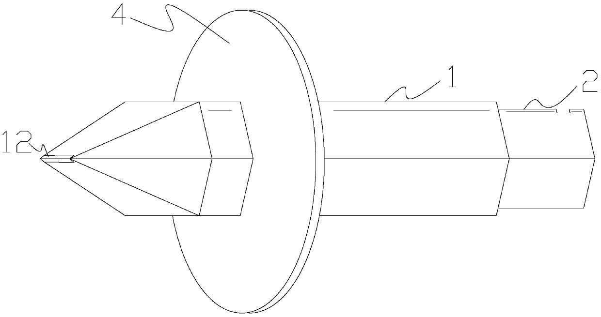
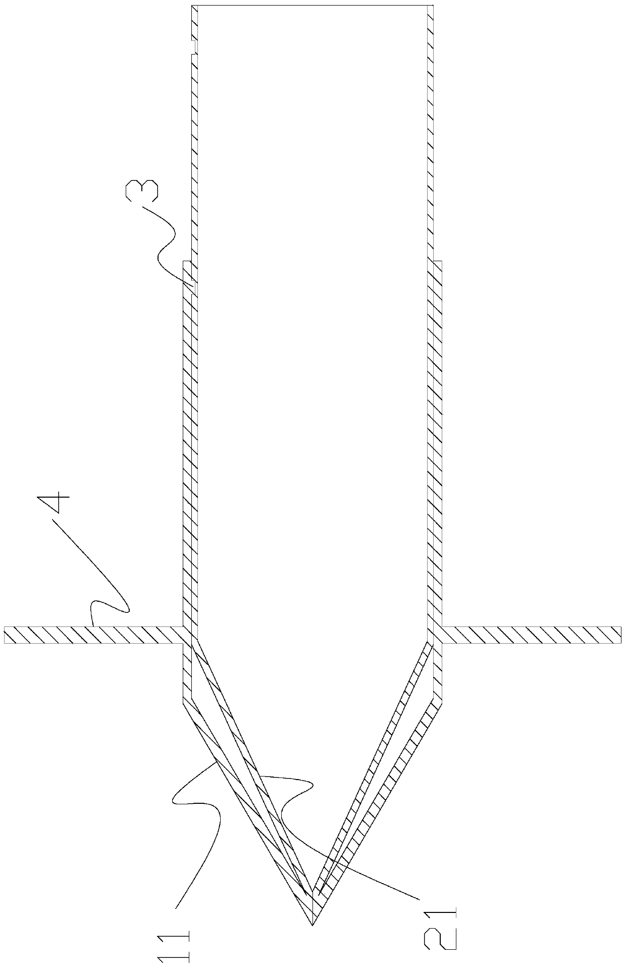
[0057] like Figure 1-Figure 6 As shown, this embodiment includes a fixed tube 1 and an inner casing 2 that is sleeved in the fixed tube 1 and can move back and forth relative to the fixed tube 1;

[0058] The fixed tube 1 is provided with at least two puncture cone outer wall assemblies 11 which are connected in rotation and arranged around the front end of the fixed tube 1 . Corresponding puncture cone inner wall assembly 21;

[0059] The puncture cone inner wall assembly 21 is slightly longer than the puncture cone outer wall assembly 11, and each puncture cone inner wall assembly 21 is rotatably connected to the front end of the corresponding puncture cone outer wall assembly 11 to form a puncture cone component unit; each puncture cone component unit arranged around the fixed tube 1 Gather to form a punctureable structure;

[0060] A locking mechanism 3 for locking or unlocking the relative moving position of the two is provided between the fixed pipe 1 and the rear wal...

Embodiment 2

[0063] like Figure 7 and Figure 8 As shown, this embodiment includes a fixed tube 1 and an inner casing 2 that is sleeved in the fixed tube 1 and can move back and forth relative to the fixed tube 1;

[0064] The fixed tube 1 is provided with at least two puncture cone outer wall assemblies 11 which are connected in rotation and arranged around the front end of the fixed tube 1 . Corresponding puncture cone inner wall assembly 21;

[0065] The puncture cone inner wall assembly 21 is slightly longer than the puncture cone outer wall assembly 11, and each puncture cone inner wall assembly 21 is rotatably connected to the front end of the corresponding puncture cone outer wall assembly 11 to form a puncture cone component unit; each puncture cone component unit arranged around the fixed tube 1 Gather to form a punctureable structure;

[0066] A locking mechanism 3 for locking or unlocking the relative moving position of the two is provided between the fixed pipe 1 and the re...

Embodiment 3

[0069] like Figure 9 As shown, this embodiment is on the basis of embodiment 1 or embodiment 2. In the lumen of the inner sleeve 2, there is only a unidirectional flow of material from the side where the puncture cone component unit is located to the other side. Check valve 22.


PUM


Abstract

The invention relates to the field of medical devices, in particular to a wall-shaped tissue puncturing and fixing device which comprises a fixing pipe and an inner sleeve sleeved with the fixing pipe and capable of moving forwards and backwards relative to the fixing pipe. At least two puncture cone outer wall assemblies connected in a rotating mode are arranged on the fixing pipe. Puncture cone inner wall assemblies are correspondingly arranged on the front end face of the inner sleeve. The puncture cone inner wall assembly is slightly longer than the puncture cone outer wall assembly. The front ends of each puncture cone inner wall assembly and the corresponding puncture cone outer wall assembly are connected in a rotating mode to form a puncture cone assembling unit. All the puncture cone assembling units distributed around the fixing pipe are gathered to form a puncturable structure. A locking mechanism is arranged between rear end pipe walls of the fixing pipe and the inner sleeve. A limiting mechanism protruding outwards is arranged outside the pipe wall of the fixing pipe. The axial distance between the limiting mechanism and the front end face of the fixing pipe is equal to or slightly larger than the thickness of wall-shaped tissue. Puncturing and fixing can be achieved at the same time without the aid of other tools, and the application range is wide.

Description

technical field [0001] The invention relates to the field of medical equipment, in particular to a wall tissue puncture and fixation device. Background technique [0002] Puncture and fixation are one of the most basic operations in surgery. Through puncture and fixation, a stable channel can be established in the human body, and subsequent drainage, puncture or closure operations can be realized through this channel. [0003] However, in the prior art, puncturing and fixation are usually performed separately. First, it is necessary to use a special puncturing tool such as a puncture cone, a puncture needle, etc. to puncture an open channel on the chest cavity, abdominal cavity or other wall-like tissues of the human body, and then Then fix the fixture on the channel. This method is cumbersome to operate and requires many surgical tools, especially in some special treatment environments, such as field medical treatment, field medical treatment, and emergency treatment, whic...

Claims


Application Information

Patent Timeline
Patent Type & Authority Patents(China)
IPC IPC(8): A61B17/34A61B17/12A61M1/00A61M3/02
CPCA61B17/12031A61B17/12099A61B17/12159A61B17/3403A61B17/3415A61B2017/3405A61B2017/347A61M1/0023A61M1/0058A61M3/02
Inventor 王格非
Owner 王洛
Why Eureka
Try Eureka